saxmonster
Well-known member
- Joined
- Jan 3, 2012
- Messages
- 534
HAHAHA OK, there are 2 IN BUTTONS, I forgot about the main one at the top.
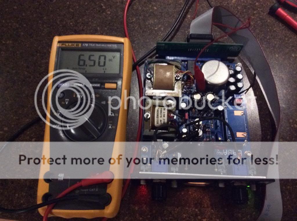
Ok when the LA3A is "OFF" The very top button, hahahahah I get -5DB on the meter with a +4DB signal feeding it. Sorry about the confusion. I always forget about the so called POWER BUTTON, hahahah
How would I adjust it so that I get -4db or should that actually be zero maybe?
Ok when the LA3A is "OFF" The very top button, hahahahah I get -5DB on the meter with a +4DB signal feeding it. Sorry about the confusion. I always forget about the so called POWER BUTTON, hahahah
How would I adjust it so that I get -4db or should that actually be zero maybe?


![Soldering Iron Kit, 120W LED Digital Advanced Solder Iron Soldering Gun kit, 110V Welding Tools, Smart Temperature Control [356℉-932℉], Extra 5pcs Tips, Auto Sleep, Temp Calibration, Orange](https://m.media-amazon.com/images/I/51sFKu9SdeL._SL500_.jpg)


")