Meanwell Modules - AH ML5000 PSU Replacement

GroupDIY Audio Forum

Help Support GroupDIY Audio Forum:

This site may earn a commission from merchant affiliate links, including eBay, Amazon, and others.
Yup. That looks fine.

One minor nit-pick though is that you don't need the traces going to the resistor in the RC to be really big. The bulk of the current in these CMs is through the emitter and collector (or collector to emitter in the -17 CM). So only those traces need to be super wide.
 
Great ! Thanks

Components are on there way, Will make those minor adjustments tomorrow and send away for the PCBs.

PCB's Updated and on there way! will update when they arrive !

Cheers
Blissy 
 
Alright So the new PCBs are installed!  :) :)

So after some quick listening it seems that the noise is suppressed. Can't hear any main hum at any volume level! of course I will confirm this with noise measurements.

A few things I overlooked. The +48v Phantom CM board. The AGND return (next to +48v Output on the CM board) were should I connect this. On the Original it uses the same return as the main AGND, however now its on its own seperate board. Should I add another ground connection to the connector PCB following the +48v and connect it there?

Also foolishly I underestimated how high these boards would be when stacked so I am working out place to mount the 48v Phantom CM.

Currently the main Pass transistors are sitting at around 70 Degrees.

Cheers
Blissy
 
Run a short wire from CONX4 of the +48V board down (or up?) to CONX6 of the +-17V board. Meaning maybe have two wires on the same female terminal. Maybe solder them instead of crimping if you have to. CONX1 and CONX2 are still supply from the +48V SMPS. But try to make all 4 wires coming out of those boards to the CPC connector close together. That should be ok.

To help with stacking maybe solder the +48V cap to the underside of the board directly to the bottom of the male terminals such that it clears the caps of the +-17V board. This assumes you put the +48V board on top of the +-17V board. It's hackish but again, you're just trying to get a POC right at this point.

Then make new wav files and we'll see where you're at.
 
squarewave said:
Run a short wire from CONX4 of the +48V board down (or up?) to CONX6 of the +-17V board. Meaning maybe have two wires on the same female terminal. Maybe solder them instead of crimping if you have to. CONX1 and CONX2 are still supply from the +48V SMPS. But try to make all 4 wires coming out of those boards to the CPC connector close together. That should be ok.

To help with stacking maybe solder the +48V cap to the underside of the board directly to the bottom of the male terminals such that it clears the caps of the +-17V board. This assumes you put the +48V board on top of the +-17V board. It's hackish but again, you're just trying to get a POC right at this point.

Then make new wav files and we'll see where you're at.

Ok, have run into some issues +/- 17v Seems to be fine however there is still noise on the phantom rail...  :'(
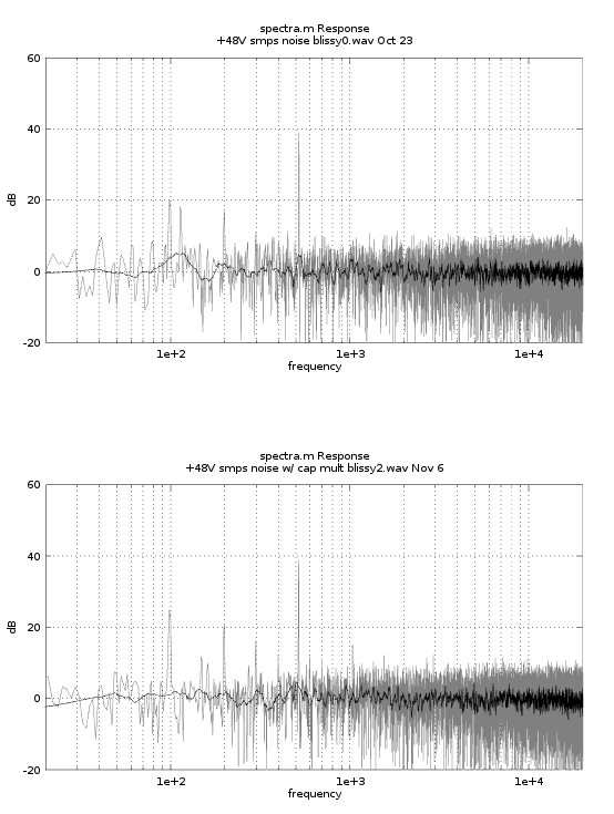
Still that component at 500hz. How can it still be there, I have a 100uf Cap and a 1K resistor in the CM. Could it be the CM is not operating as it should ? Using the D45HG8, FZT651QTA and a 1n4004.

Also confirming I have the Output of the Original CLC filter Feeding the input of the new CM filter PCB

Ok here is a sample of the noise on the DO of one of the channel with phantom engaged and gain at MAX. would be good to compare noise results to confirm CM is actually doing anything. Is it Possible that the CM is not efficient at these higher freqs?


https://drive.google.com/file/d/1IE8S3afBSk_uMGiRtY1SaqxmaWxBiILb/view?usp=sharing

Cheers
Blissy
 
I have been thinking about the Phantom Rail Issue. Could it be that the Ripple is being superimposed on the output due to a grounding issue or possibly the load resistors placement in the circuit?

Playing round and found adding a 1000uf Cap across the output of the CM removes all noise on the phantom rail 
 
Blissy said:
I have been thinking about the Phantom Rail Issue. Could it be that the Ripple is being superimposed on the output due to a grounding issue or possibly the load resistors placement in the circuit?

Playing round and found adding a 1000uf Cap across the output of the CM removes all noise on the phantom rail

Post a wav. A 1k/100u CM should give you decent attenuation but it's just not at all:

blissy2.png


No difference. It could be that the impedance between pin 1 of your mic input and the "star" ground of you're new supply is a little two high. Maybe measure with a meter but account for baseline resistance of your meter (probes shorted together). Or you're supply wiring isn't quite right somehow and your CM is really not having any effect at all. Not sure what you could do to do that though. Or maybe the noise generated by the SMPS is just inserting noise into the ground somehow such that the CM is having no effect but again I'm sort of blanking on why that would be.

But post a wav with the 1000u cap and we'll see if really removed all of the noise or what.

Otherwise, you could always get one of the other SMPS that I mentioned.

Also maybe post wav files for your +-17. Might as well be objective and honest about the result or this is all quite pointless.
 
squarewave said:
Post a wav. A 1k/100u CM should give you decent attenuation but it's just not at all:

blissy2.png


No difference. It could be that the impedance between pin 1 of your mic input and the "star" ground of you're new supply is a little two high. Maybe measure with a meter but account for baseline resistance of your meter (probes shorted together). Or you're supply wiring isn't quite right somehow and your CM is really not having any effect at all. Not sure what you could do to do that though. Or maybe the noise generated by the SMPS is just inserting noise into the ground somehow such that the CM is having no effect but again I'm sort of blanking on why that would be.

But post a wav with the 1000u cap and we'll see if really removed all of the noise or what.

Otherwise, you could always get one of the other SMPS that I mentioned.

Also maybe post wav files for your +-17. Might as well be objective and honest about the result or this is all quite pointless.

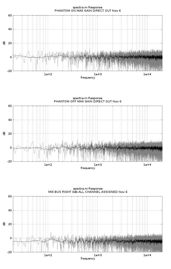
For Sure :) I have done three Measurements. all phantom measurements are with the 1000uf Cap Across the output of the CM

1. Phantom On Gain at MAX fader at 0 Direct out
2. Phantom Off Gain at MAX fader at 0 Direct out
3. All Channels Assigned Fader at 0 Mix Bus Right

https://drive.google.com/drive/folders/1MfDPk01bYT_SqWIVEBGotfCEBlmXp8U3?usp=sharing

Cheers
Blissy
 
Blissy said:
For Sure :) I have done three Measurements. all phantom measurements are with the 1000uf Cap Across the output of the CM

1. Phantom On Gain at MAX fader at 0 Direct out
2. Phantom Off Gain at MAX fader at 0 Direct out
3. All Channels Assigned Fader at 0 Mix Bus Right
That looks good. Just to be clear, this is your new custom supply?

blissy3.png


I don't see any mains at all really.
 
Correct this is the new supply! With the 1000uf Cap across the output of the phantom CM.
Do you see any issue leaving that cap in place?. Placing it before the CM does not remove the Noise only when inserted across the output of the CM. Interesting.

Oh boy, Seeing those graphs is definitely a relief!

Cheers
Blissy
 
Yeah, I guess it's ok. The CM should only "turn on" as fast as the RC so even with the big cap on the output it should limit startup currents and stop output protection from kicking in.

Maybe the emitter resistance of the pass transistor was at play. I'm not absolutely certain as to why that made such a big difference honestly. But yeah, it looks like it's working though.

You did it!
 
squarewave said:
Yeah, I guess it's ok. The CM should only "turn on" as fast as the RC so even with the big cap on the output it should limit startup currents and stop output protection from kicking in.

Maybe the emitter resistance of the pass transistor was at play. I'm not absolutely certain as to why that made such a big difference honestly. But yeah, it looks like it's working though.

You did it!

YAY!!  :D :D :D
Huge Thankyou squarewave! I really appreciate all your help and time you have given to this project! and putting up with my novice electronics knowledge and endless question. Thank you.

Anyone who looking to do a smiliar thing please don't hesitate to ask any questions happy to provide anything that may be helpful and to support this fantastic forum!

Thanks
Blissy 
 
I've been following this thread with great interest!
Well done guys!

Now you got me thinking to do the same for my Soundcraft Sapphyre console.

At some point I wasn't able to wrap my head around the concept of connecting CM board. Does it completely replace inductor and capacitor, or it just replaces capacitor in the LC filter circuit leaving the inductor still in the circuit?

Blissy, are those filter schematics on your gdrive final version? It was a bit tough to follow all the versions since you deleted older versions and replaced them with new ones. I guess this is it, right?

:)

Luka
 
You could just do a capacitance multiplier (CM). Originally the hope was that the LC would be enough. But what we learned from all of this is that the higher current SMPS have significant low-frequency noise. At least the LRS series modules appear to have a really serious 500Hz component as well as mains harmonics. So that necessitated a CM which but that gets high frequencies as well as really low frequencies so the LC probably isn't necessary. What we also learned was that apparently a large filter cap on the output of the CM is necessary. I'm not perfectly clear as to why but I suspect it's because of emitter resistance of the pass transistor.

So in summary, you can probably do just SMPS > CM > filter cap. But proper wiring (especially ground wires converting at said filter caps) is also important. If you decide to do a console SMPS supply start a thread with schematics / pics / details and maybe I'll do a new diagram that includes the filter caps.
 
squarewave said:
If you decide to do a console SMPS supply start a thread with schematics / pics / details and maybe I'll do a new diagram that includes the filter caps.

Yes I'll do that!
In next few days I will research more on my console psu demands and do a search on what's available to buy locally.
I was hoping you'll be willing to chime in and help! Thanks!
:)

L
 
shot said:
I've been following this thread with great interest!
Well done guys!

Now you got me thinking to do the same for my Soundcraft Sapphyre console.

At some point I wasn't able to wrap my head around the concept of connecting CM board. Does it completely replace inductor and capacitor, or it just replaces capacitor in the LC filter circuit leaving the inductor still in the circuit?

Blissy, are those filter schematics on your gdrive final version? It was a bit tough to follow all the versions since you deleted older versions and replaced them with new ones. I guess this is it, right?

:)

Luka

Hey Shot,

Correct the schematics on the drive are the final ones, any questions shoot me a message or I'll pop over to your thread :)

Only ended up needing that extra Filter cap on the 48V. It might be worth looking at a different SMPS Module than the one I used for 48v rail I believe squarewave mentioned alternatives earlier in the thread.

Cheers
Blissy
 
Thanks for the support!

It'll take some time for me to open my thread and get into this journey. I have to find what connector type is used on original psu and get a replacement for it. I don't want to take out the connector from existing psu since I plan to continue using it while I build new psu. I'll just plug the same cable from one to another psu.
Stay tuned!

:)

Luka
 
Back
Top