Minimal Headphones Amp

GroupDIY Audio Forum

Help Support GroupDIY Audio Forum:

This site may earn a commission from merchant affiliate links, including eBay, Amazon, and others.
Any reason to not use a dedicated headphone driver IC, like the TPA122?
perhaps OK for modest power into 32 ohm cans, but won't melt ear wax at 600 ohms with a 6V max power supply.

I ran into a similar PS issue in my last generation drum tuner when I used a class D IC to drive two loudspeakers loud enough to excite drumhead resonances. I had to add a discrete pre regulator to not exceed the amp's max PS voltage.

Since this is the WWW there will be many purists pushing esoteric high end headphone amps.

===

for chuckles I just looked up the data sheet for the LM377 I used in that DJ mixer kit back in the 70s. it was a 2W chip and long since obsolete.

perhaps replaced by LM1877 and LM2877 the latter which specs 4W into 8 ohms... and 24v rails and perhaps still in production. These are only stable at gains of 10x or higher so needs to be tricked for less than 10x.

JR
 
Yes please,

Cheers

Ian

There are several shops offering these boards, the cheapest (20€) I found is:
ZEROZONE Finshed Ver JLH Class A 1969 Headphone amplifier PRE AMP board

These shops want twice as much or more for the same thing (about 50€):
Class A Dual Channel Single-ended Headphone AMP Amplifier Board For JHL

This one might be an improved version (40€)?:
JHL Klasse A Vorverstärker AMP Board Dual-kanal Single-ended AC12V+12V 12~120kHZ

Different, more expensive (67€):
Lehmann Class A Headphone Amplifier LEM Preamplifier Kit/Board With Protection
One Pair Beta 22 Class A Headphone Amplifier Kit / β22 Headphone Amp Board DIY

Different, cheap, modern design, maybe worth a shot for 10€:
Audio Signal Preamplifier Board DIY Home Theater Headphone Driver Mini Amp
12V-24V TPA6120A2 TPA6120 Headphone Amplifier Board AC/DC HIFI Headphone AMP

Once you start digging there's a lot on the market.

This might be the schematic of the board I have. I just googled it, it didn't come with the board. It might not be exactly what I got, but it looks correct at first glance.

jhl-headphone-amp-mki-schematic_686655.jpg

What might work as well could be small IC based power amp pcbs? There's a lot of decent stuff out there. The available supply voltage might matter though.

As mentioned already, there are also modern IC solutions which might be suitable, but I have no experience with these.

I hope that the links work, I've included the name of the listings in case you'd have to search ;-)

Aliexpress and other Chinese sources will have similiar offerings.

Cheers,

Michael
 
In this instance the actual phones are specified as 63 ohms at 1KHz and a sensitivity of 106dB/mW.

To convert to something more useful, 118dB/1V.

The 63 Ohm impedance means that single OP-Amp's need to be video types intended to drive 50 Ohm terminated transmission lines. Most of the good ones are sadly long NRND/EOL.

One that remains is:

Texas Instruments LM6172IN/NOPB

It's a bit noisy, at ~ 2uV self noise (that is only -114dBV). In a sufficiently low impedance circuit (offset & current noise) it will nevertheless do. It will start being current limited into loads lower than 140 Ohm.

If you ask me, mak the Headphone Amp more universal.

Use OPA1678 (Dual) or NE5532/34 with external BD139/140 pair (or TO-220 analogs from JP) with 1Ohm emitter resistors (see Neve BA640 reference).

1693993953987.png

Use a conventional bias spreader (not diodes) with a second NPN transistor on the same heatsink as the output pair.

7812/7912 as power supply and protection (overcurrent) for output stage, 7815/7915 for Op-Amp (or 18V/15V)

Quiescent current minimum 26mA up to 100mA (that gives full Class A into 63 Ohm).

Inverting mode feedback volume control.

Optional input buffer (Op-Amp) for high impedance input (> 10k), this could also be used for some bass boost EQ (again use a center neutral toggle for two levels of boost) and crossfeed might be implemented there as well (again, with ceter neutral toggle switch to handle off, stage 1 & stage 2.

For extra brownie points, solderdude's "Kamaeleon" EQ can be integrated around an inverting Op-Amp, with plug in cards possible for almost any headphone under the sun:

Kameleon

I'd still fit the gain switch like I showed, can be implemented with a center neutral M7 toggle switch.

The result will handle 95% of all headphones great. With 7812/7912 per channel, ~ 1A peak @ 12V is possible so a 12Ohm headphone can be driven to maximimum output.

If you make a small PCB for it , including a pair of 6.3mm PCB Jacks, one direct (modern low impedance headphones) and one with 120 Ohm build out (older high impedance dynamic headphones that sound midtlrange emphasised from < 1Ohm sources).

Add gain switch and Volume pot you have a great universal HP Amp that can easily be made no matter what supply situations are for specific parts.

And it handles almost anything, as you could build it with +/-22V Rails for headphones that need high output and with (say) OPA1611 for super low noise for extra sensitive headphones and with lower voltage rails.

I'd include rectifiers, supply caps, footprints for double single OPA (including DIP8 and SOIC8) and single Dual OPA. Just add AC or DC...

This allows anything from a 5532 to double OPA828 (or OPA627 in metal can, if you have some) Op-Amp.

Add footprints that can take TO-126 and TO-220 outputs, again, maximum flexibility.

Footprints for different potentiometers, from RK-9, RK-16, Rak-27 ALPS and generic types.

You could probably easily get a huge group order for this if you also offer it on Headfi...

Thor
 
Last edited:
This has been a really interesting thread ,
I was aware of the limitations of low powered H/P amps a long time , my answer was 2x EL84's , SE triode connected , transformer coupled , with a 3 ohm secondary winding .
 
I stand by my original advice but with a known target headphone my inner engineer is thinking of tweaks.

-With a class A/B driver stage buffer one could increase the class A bias high enough to keep small signal audio very clean.

-An op amp trick that I never used but many have written about over the years, an IC driver can be tricked to operate class A by hanging a resistor to one rail or the other from the output. This could perhaps improve one of the modern canned headphone amp ICs.

I would definitely try to bench test both of these with a load, to see if they even work.

JR
 
-An op amp trick that I never used but many have written about over the years, an IC driver can be tricked to operate class A by hanging a resistor to one rail or the other from the output.

If you look at the Neve BA640, this is used there, and quite smartly.

R5 is bootstrapped by C5, so the resistor chain R5/R6 will draw ~2.5mA out of the output (and through the Emitter follower on the 5534 output), but the value is "bootstrapped" so that resistor does not load down the output.

1694018521855.png

This could perhaps improve one of the modern canned headphone amp ICs.

Generally speaking, no.

The majority of these are for laptops, computer motherboards and the like and the performance is best described as "functional".

Internals are often highly optimised CMOS with source linked to the rails (to allow the most swing with low voltages), "class A" bias actually at best does nothing or unbalances a highly optimised circuit.

Thor

PS, people do change headphones, so even a known target is likely over time a "moving target"...
 
Trying not to feed this veer that I am apparently feeding, yes the low voltage parts are CMOS, but some of the others parts discussed are clearly bipolar with probably class A/B output stages inside.

If pursuing IC tricks, defer to your test bench to confirm whether a tweak works or not. Ignore overly broad sweeping conclusions.

JR
 
Last edited:
Trying not to feed this veer that I am apparently feeding, yes the low voltage parts are CMOS, but some of the others parts discussed are clearly bipolar with probably class A/B output stages inside.

Okay, we get a number of parts marketed as "Headphone Amp".

On one end we have general purpose Op-Amp's with beefy output stages like the NJM4556 that CAN BE USED as headphone Amp's, others like the TI TP6120 are literally just resymbolised Video or ADSL Line driver IC's (TPA6120 = same die as THS6012).

There are also many higher current OP-Amp's (e.g. OPA554 - nice FET input type) and lower power Speaker Amplifier IC's (e.g. TDA2030 or LM1875) that are usable as Headphone amplifier.

These are often bipolar, be it cost (NJM) or in video/adsl circuits the need for speed. These commonly have complementary bipolar emitter followers as output stages and usually can only swing to around 2V below rails.

Class A biasing on these can work, I have used TPA6120 with additional pull down resistors to -V which reduced thermal distortion and also crossover distortion measurably.

Performance of these is also quite variable, the NJM4556 is subjectively quite poor, while TPA6120/THS6012 is excellent and even better in a multi-loop design (actually anything is pretty good in a multiloop design if the input op-amp is good.

On the other end we have "Headphone Amplifiers" for consumer gear, usually smartphones, laptops, computer motherboards.

These are low voltage single supply parts often with additional integrated functionality. In the case of the TI TPA6130 you have a serially controlled volume control and a charge pump to produce an on-chip negative rail.

The MAX97220 also has this on board charge pump but is more flexible, you can even disable the charge pump and feed it with +/- 5.5V or you can use the negative rail to feed other IC's as well, if the current draw is low.

These IC's all tend to be CMOS designs and use "grounded source" output topologies as this allows rail-to-rail output. If you have (say) a +3.3V Rail and make a -3.2V Rail using a charge pump, you cannot afford to loose 2V swing on either side. They are also designed for lowest possible power consumption as they commonly find themselves in battery powered gear.

For these it is actually important to not unbalance the whole circuit current wise, usually "class A" bias makes them worse. Performance is somewhere between pretty poor to semi-decent.

What makes them better are "arrays" and multi-loop topology.

Given the MAX97220 has a 2.5kU price of 71 cent, you can use 2pcs per channel in parallel which quadruples output current so you drive 3.7V into 16 Ohm and adding a OPA1678 for 35 cent to give very low noise and distortion. BOM cost for a stereo version is way below 5 USD in volume. The M/S trick could be applied to get even more output voltage, not enough for the drummer, mind you.

This all makes1694028375631.png for a tiny system (fraction of a credit card) that can run via a small step-up switcher and charger IC with a single 3.7V Lipo Cell (which it can change from USB) for a complete headphone Amp with enough output for most sensible headphones, 1uV self noise and tripple zero THD. With under 5 USD BOM without Lipo battery.

Not a DIY project though, I'm afraid. As remarked, these are usually in SMT packages that are tiny and hard to solder and DIY unfriendly. It's the kind of stuff I design for commercial products.

This PCB is slightly larger than a credit card, It could obviously have been smaller, but it was designed to fit existing casework. On my screen this is actual size.

A row of 4pcs MAX 97220 above white sticky label.

Multiple 74HC4053 Analogue 1694029518182.jpegswitches and a 95 step 1dB per stepped attenuator IC and a Quad Op-Amp (OPA1679) are above.

A small CPU controlling everything on the left (with green dot) and battery charger / step-up switcher (5.5V/1.5A output) left top corner.

This HP Amp has multiple EQ options and crossfeed, plus a wide range of gain switching tied into the volume control, unity gain to +18dB. Portable with battery and with Bluetooth Module on the other side.

Not to show off, but to show how a 21st version using these "Headphone Amp" IC's look like.


Here in da box, with credit card for size comparison...

Thor
 
Last edited:
I did a build on veroboard based on the CMoy except with an OPA2134 on the front end with a single NJM4556 driving the output. Admittedly, I only had 250-600 ohm cans available for testing, but it sounded good to my ears.

My 'CAN's are Fostex T50RP (modified). They are much more resolving than typical dynamic 'can's.
I would use the current dumper configuration I showed a few posts back.

The thing I like about the buffer chips is that you can wrap them inside the feedback loop of an opamp and they take care of all the mess of biasing an output stage for you plus you get built in protection.

Not all of the Buffer chip's are sufficiently protected. Biasing - yes, but biasing is frequently "cold" and not adjustable. Cost and availability are also an issue.

You could always do a BD139/BD140 based output stage too. CAPI does a headphone amp that uses a TIP41/TIP42 pair with an OPA134 driver.

Capi looks good:

Classic Audio Products, Inc.

TIP41/42 are a bit slow. Better choices exist, make the buffer fast enough to not need you to mess with extra frequency compensation. But it is similar to what I suggested before as "universal HP Amp". It would likely make a good community project.

I know I have seen several designs based on similar topologies so a current boosted opamp is a sensible approach to drive most headphones.
1694032254543.pngMany excellent reviews and tests and awards... iFi Zen CAN.
4-Channels each with BCP53/56 which are SMT versions of BD139/140.

It is largely based on the Neve BA640 design but with a VBE multiplier for biasing. It uses fixed resistors for biasing (no adjustment needed) and is mass production reliable with that.

Near the volume control OPA1679 - with these available and necessary adapters for DIP footprints there is no possible excuse for using TL07X.

Multiple 74HC4053 for gain and EQ switching.


It's on my desk right now and even sees use with my 4.5k USD Abyss Diana Headphones (no kidding).

The main advantage of using Op-Amp and discrete transistors is that if the precise part is unavailable, there are usual identical parts from a handful of vendors and comparable parts galore.

I learned the hard way to minimise the use of vendor specific IC's over generica and discretes. Use generica/discretes wherever you can is my suggestion.

Plus you control the tradeoff's between dissipation/cooling, linearity into lower loads and so on - the way nothing canned offers you..

Thor
 
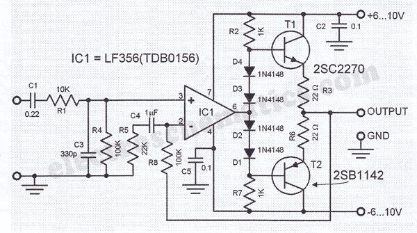
I had built something similar to this on a breadboard when I needed a 4-channel headphone amp:

hifi-headphone-amplifier.gif


with some slight differences due to parts on hand: +-12V supply, op-amp was OPA2134, output devices were MJE171/181 pairs, and R3/R6 were increased to 33 ohms. What I recall was that it output an obscene amount of power into 32 ohm headphones, even after decreasing the gain. It also howled at ultrasonic frequencies which was cured by bypassing R8.

I came out of it thinking that it was way overkill for my purposes, and ended up just paralleling some op-amps with build-out resistors just like Ian proposed. :)
 
I really do not care what pair of cans you're listening with. Continuing down this path and this will turn into nothing more than a mess of a thread with no clear end. At the end of the day what is going to matter is which set of compromises best suit the requirement (power, space, cost, etc...).

Ruffrecords mentioned he was looking for some NJM4556s. I happen to have some on hand and am willing to part with them, and subjectively I do not mind their sound. They are at least worth a try as they may or may not be adequate. All I did was offer some viable and simple methods of constructing a headphone amp. That is all. No need to interject your opinion on everyone's post with your two cents.
Thanks for the offer of NJM4556s. They seem to be used in many headphone amp designs and are mostly well liked. (Thor has very special ears).

I decided to bite the bullet and buy some from Mouser. Good thing is they are pin compatible with NE5532 and many other dual op amps I could try in this configuation. I plan to try several types to find out if I can hear any difference but my ears are 72 years old so maybe not. :(

Cheers

Ian
 
Back
Top