Mix Bus Compressor from scratch

GroupDIY Audio Forum

Help Support GroupDIY Audio Forum:

This site may earn a commission from merchant affiliate links, including eBay, Amazon, and others.
Best to read the whole thread first. This compressor will only give around 6dB which will be fine for its intended use for the mix bus. You sound like you might need more than that and there are better designs out there than this.
With a simple power supply all you have to worry about is 50Hz and a few harmonics. Switch mode power supplies are only for the brave.
Best
DaveP


There are specialized ic's to create mathematical correct sine waves at whatever freq.
But also carry specialized datasheets!

I'll will try with a salvaged transformer from a USB charger, a shop gave me.
running in reverse, curious to know what it yields, using wien bridge osc.

salvaged transformer: there is a companies name on there, it indeed makes "complete" USB charges, even the part number refers to compete USB charger, but nothing indicated they sell transformers, so no datasheet.

in the USB charges you have the same 323V problem after bridge rect (some guy on tube showed that and told about that).
These transformers are build for that, but the catalog is really big.
 
Last edited:
I'm getting a little confused about this recent piece of the discussion. Is this input actually relevant to DaveP's development of this design? It seems like a totally separate train of thought has entered the conversation and it isn't connecting for me. I'm not trying to be snarky, I'm honestly confused.
 
Best to read the whole thread first. This compressor will only give around 6dB which will be fine for its intended use for the mix bus. You sound like you might need more than that and there are better designs out there than this.
With a simple power supply all you have to worry about is 50Hz and a few harmonics. Switch mode power supplies are only for the brave.
Best
DaveP


Maybe you should try building a linear Mosfet voltage regulator.
try to create these 270V with voltage dividers and zeners, somehow.
Would that more efficient and less heat?
 
Or else, you could just use two small 220-12 (or, if you can find them, 220-6; or the 110V-versions if you are in America or something) and connect the secondaries together, and then you can also power the heaters from there.
At the last stage, you could either just rectify it (220V) or use a voltage doubler (110V).
Voltages will be slightly less because the heaters get connected along the way (if your transformer is small enough) and the system is not that efficient (without the power restistors!).
(I hope this made sense ;) )
And, those halogen transformers or whatever may work, are quite cheap.
 
I don't have a problem with heat in the power supply or anywhere else. I am at the point of finishing this project off now, so I will not be making a new power supply. If this is what you are interested in, then please feel free to start your own thread on the subject.
best
DaveP

Just an suggestion to create the 270V exactly or very close.
Than i would be interested if you would measure across the resistors above the tubes with your scope.
To see what i would be looking at when I'm so far.

This guy runs 12AX7 on 12 volts.


Just curious, does it needs micro or milli amps, since the plates are not connected to gnd.
 
Or else, you could just use two small 220-12 (or, if you can find them, 220-6; or the 110V-versions if you are in America or something) and connect the secondaries together, and then you can also power the heaters from there.
At the last stage, you could either just rectify it (220V) or use a voltage doubler (110V).
Voltages will be slightly less because the heaters get connected along the way (if your transformer is small enough) and the system is not that efficient (without the power restistors!).
(I hope this made sense ;) )
And, those halogen transformers or whatever may work, are quite cheap.

I have such setup 220V - 15V laying around for testing purpose, when i measured, i put 223V in and got 208V ac out, unloaded.
 
Or else, you could just use two small 220-12 (or, if you can find them, 220-6; or the 110V-versions if you are in America or something) and connect the secondaries together, and then you can also power the heaters from there.
I used this technique 14 years ago and although it works, the transformers get too hot for my liking.

Regarding the video:
This forum has many members that are very clever and they actually know what they are talking about (I know because I have learnt from them).
My advice is to avoid videos like that and to read as many posts as you can from the experts on this forum.
best
DaveP
 
I know Sam's video's. They are good fun, and some of the electronic music is quite good and that museum surely is interesting, but it's not for more 'serious' studio equipment like this, in my opinion.
 
I used this technique 14 years ago and although it works, the transformers get too hot for my liking.

Regarding the video:
This forum has many members that are very clever and they actually know what they are talking about (I know because I have learnt from them).
My advice is to avoid videos like that and to read as many posts as you can from the experts on this forum.
best
DaveP


I wanna try this, with a salvaged "yellow" transformer from a USB charger for tubes in reverse.
People use this in their solar panel inverters to create 220V from 48V DC or so.

h-bridge.jpeg

at least i wanna try, maybe it works.
 
I'm getting a little confused about this recent piece of the discussion. Is this input actually relevant to DaveP's development of this design? It seems like a totally separate train of thought has entered the conversation and it isn't connecting for me. I'm not trying to be snarky, I'm honestly confused.

General Discussions are for the DRAWING BOARD and that is where your posts should be in my opinion.
Dynamic Processors is for SPECIFIC PROJECTS and that is why The Mix Bus compressor is here.

I should not really have to explain this to someone who has made 562 posts already, but maybe you need reminding of the protocol.
DaveP
 
Last edited:
General Discussions are for the DRAWING BOARD and that is where your posts should be in my opinion.
Dynamic Processors is for SPECIFIC PROJECTS and that is why The Mix Bus compressor is here.

I should not really have to explain this to someone who has made 562 posts already, but maybe you need reminding of the protocol.
DaveP


We might differ on opinion.
But burning/wasting 50V with a resistor?

Otherwise i like your project, can't wait till i free up resources to buy tubes.
 
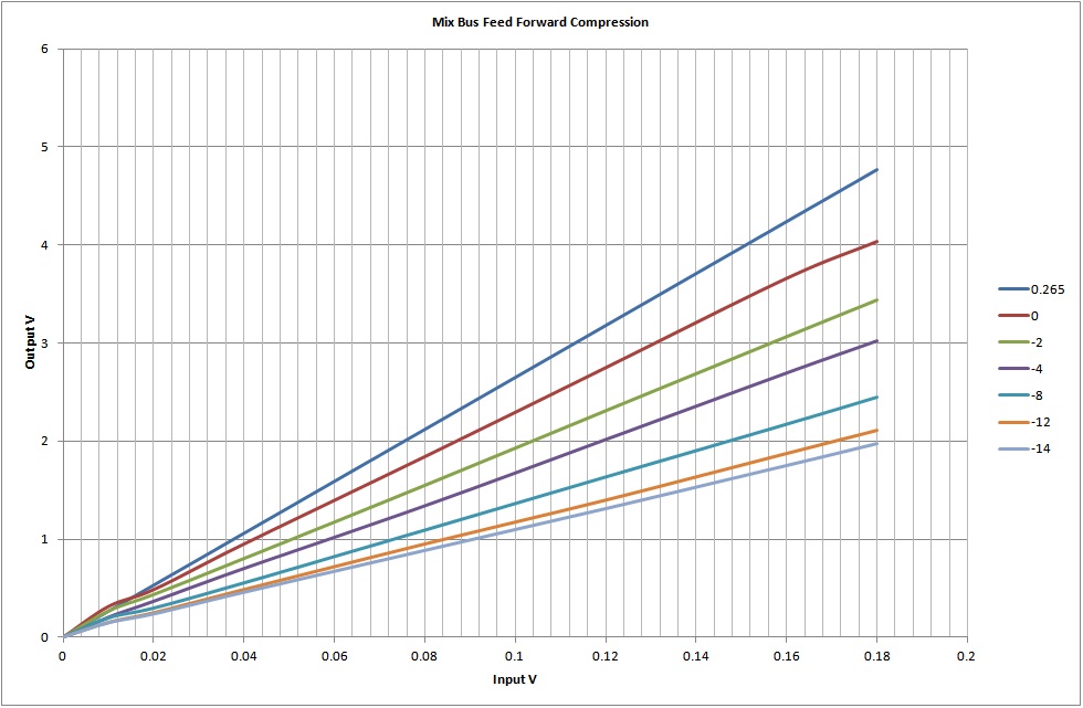
I have now completed the compression tests with the new Feed Forward arrangement, the first thing to notice is there is no "knee".

The threshold was set at different points and then inputs and outputs measured.
The Threshold at 100% gave a grid resistor dc level of 0.265Vdc
At 88% it gave 0.00V
At 77% it gave -2V
At 66% it gave -4V
At 45% it gave -8V
At 23% it gave -12V
At 12% it gave -14V which is the maximum negative possible.
best
DaveP
 
There should be at least 0.6V of threshold?
This morning its showing 0.4V, as the threshold is lowered, it passes through zero before going negative.

AC gain before threshold =threshold
DC gain after rect = ratio
It is quite difficult to measure the AC gain accurately because the input voltages are so small (10mV) and that is on the limit of what the input pot will hold steady.
I have got results between 26-31 for the gain before threshold (I used 26)

Thank you for your help and advice, its much appreciated.
best
DaveP
 

Latest posts

Back
Top