Time to give some figures:
The compressor has two stages/channel. The EF83 input tube and the 6DT8/E83F output stage.
Starting with the output stage connected to a 600 ohm resistance load. 330mVrms input to the E83F gives an output to the OPT of 7.84Vrms, this corresponds to an OPT output into 600 ohms of 1.22Vrms and approximately 0VU on the meter.
7.84Vrms is ~22Vp-p and the threshold is capable of reacting to this if it is dialled-in. The output stage has a lot of headroom, and the input can be increased up to 1.5V before any serious waveform bending takes place, but bending the VU meter needle is another thing altogether!
I have added these voltages to the schematic to make it easier to follow.
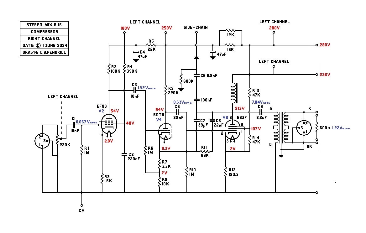
The EF83 needs an input of 67mV to give an output of 1.32V, which becomes the 330mV at the input of the E83F, the NFB in the output stage is responsible for this reduction. The EF83 is capable of giving an output of over 10V without visible distortion, but this would totally overload the output stage, it is nevertheless a useful overload margin. These figures were all obtained with the threshold turned to maximum (no compression), but use of the threshold control would allow higher inputs than 67mV without overloading the output stage.
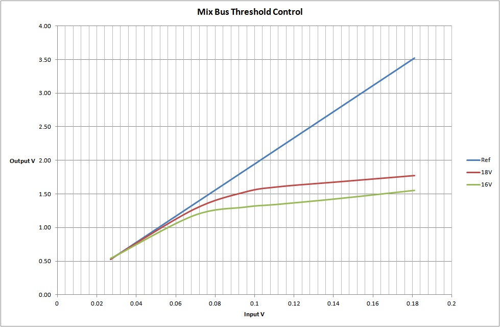
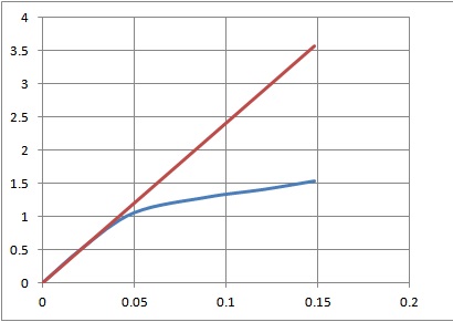
Next I will try to explore the compression characteristics.
best
DaveP


![Soldering Iron Kit, 120W LED Digital Advanced Solder Iron Soldering Gun kit, 110V Welding Tools, Smart Temperature Control [356℉-932℉], Extra 5pcs Tips, Auto Sleep, Temp Calibration, Orange](https://m.media-amazon.com/images/I/51sFKu9SdeL._SL500_.jpg)


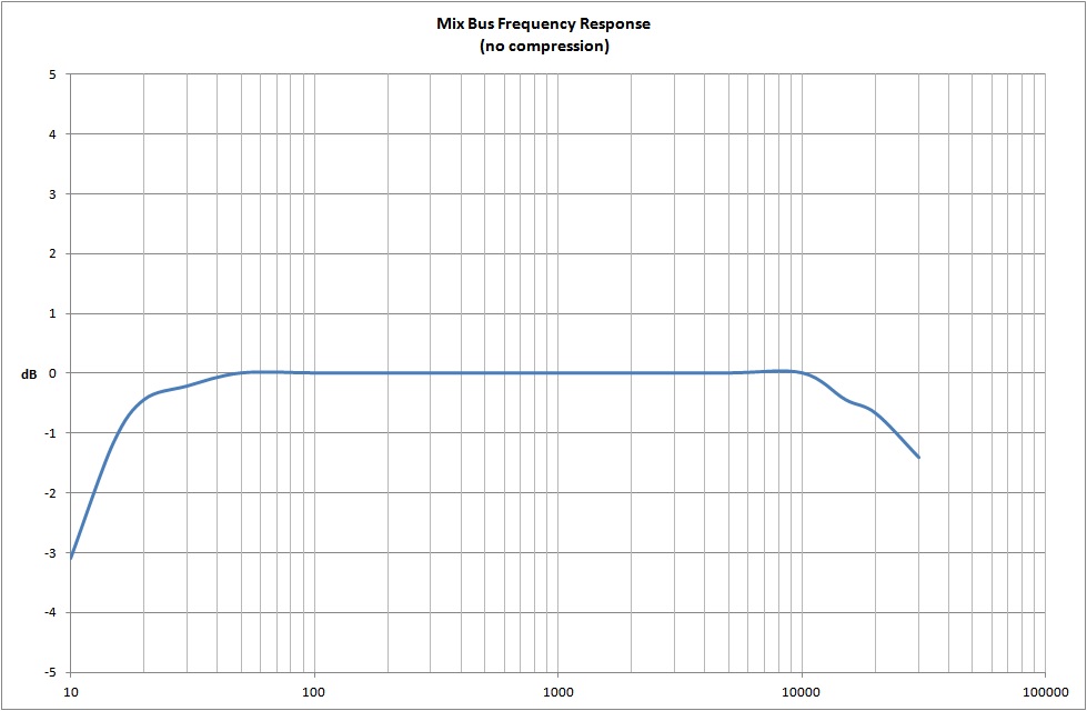
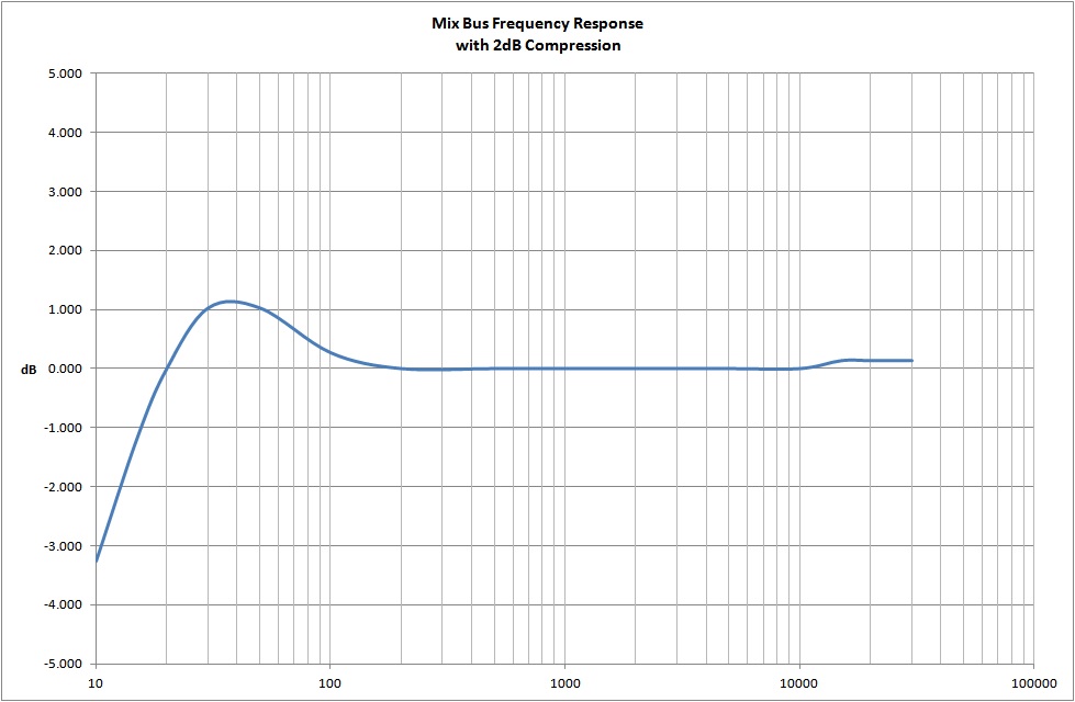
") Weird the HF response becomes flat under compression !
Weird the HF response becomes flat under compression !