Mix Bus Compressor from scratch

GroupDIY Audio Forum

Help Support GroupDIY Audio Forum:

This site may earn a commission from merchant affiliate links, including eBay, Amazon, and others.
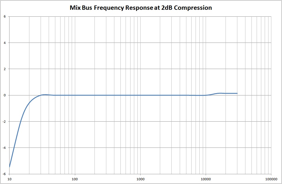
I've had time to adjust the frequency response under 2dB compression, it now looks like this:-

The original high-pass components for the side-chain were 6.8nF/680k which worked out at 34Hz, this is what caused the 1dB bump ~40Hz.
To make it flat I changed the 6.8nF for 22nF which works out at 10.6Hz, this may make the "Thump" resistance worse, we shall see.
best
DaveP
 
Thank you Thomas, I do my best.

My final problem is the feedback in the side chain, I need some ideas to tame this.
I remember making an Altec 436 that was unstable a long while ago, it would break into a low frequency oscillation, particularly if you tried to reduce the attack time, any ideas welcome.
best
DaveP
 
These are both interesting comments, Thomas you are probably right in that the side chain does not have enough power to fully control the process.
Gyraf, you have given me a few ideas, I have attached the circuit of the Philips EL3552, which is a feedforward design. I will give it a try.
best
DaveP
 

Attachments

  • philips-EL3552.pdf
    281.5 KB
..or simply run it feed-forward..?
Bravo Gyraf, this works! By using the existing side chain fed from the input, I can get some trouble free compression. The 6DT8 tube gives a gain of 35 which does not generate enough -ve voltage, but I can reconfigure the tubes for more gain. I'm not sure how I can keep the channels isolated either, with a single side chain, but maybe someone has some ideas on that. A good days work!
best
DaveP
 
Last edited:
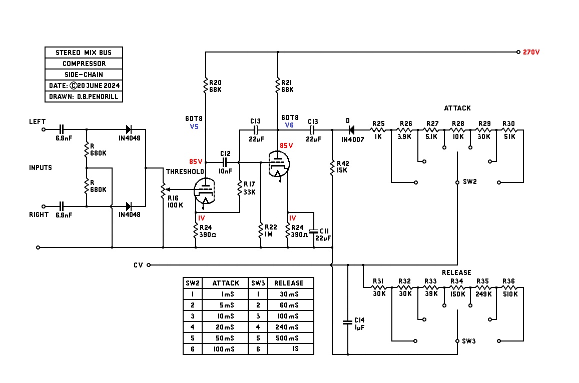
This is the redesigned side-chain amp (still using the same tubes)

The output Z of the 6DT8 is around 13K before feedback and about 550 ohms with NFB so it still has the power to drive the negative supply.
The input circuits seem to avoid crosstalk OK. This is not the final circuit as it needs refining to get the best out of it, but it works.
best
DaveP
 
I have made a few adjustments to improve the performance of the side chain.
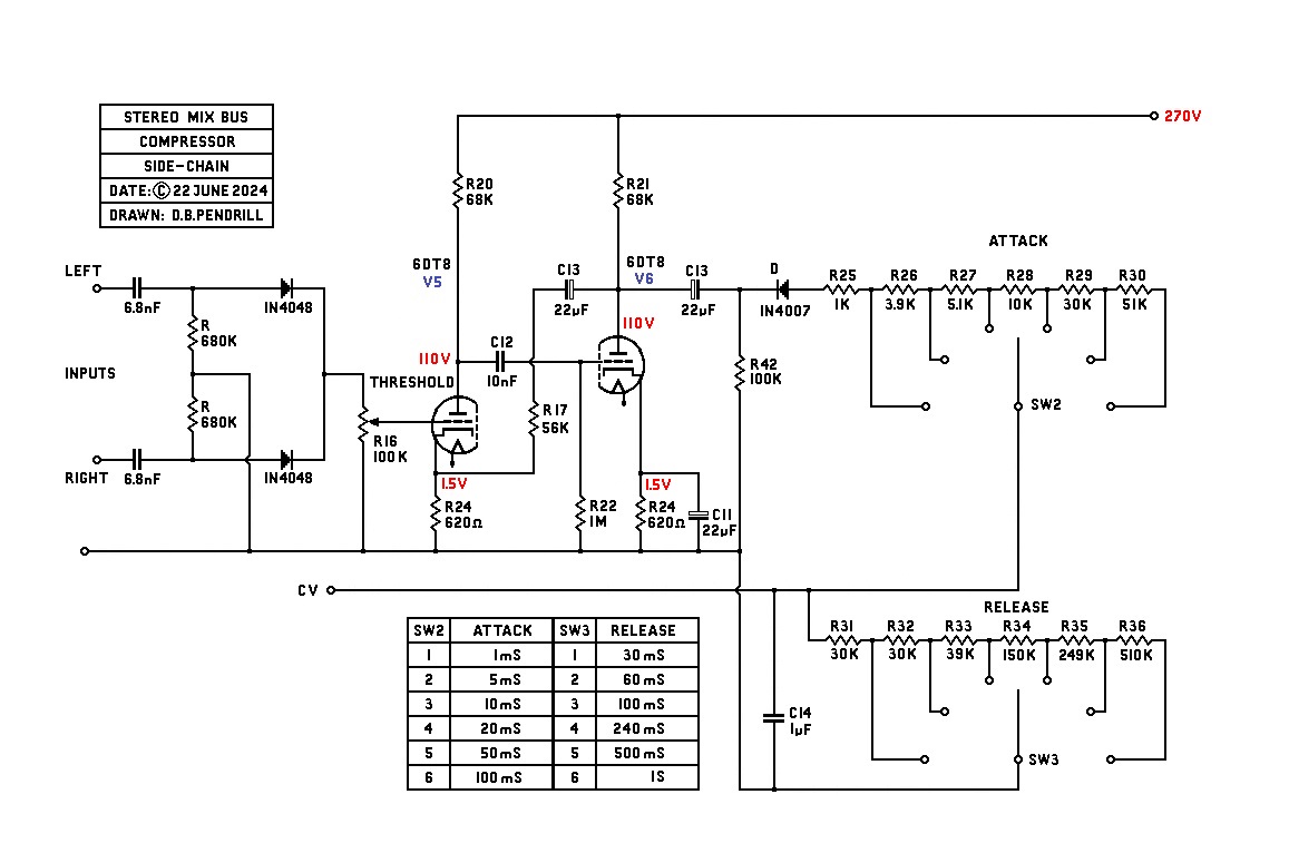
The input to either channel needs to be about 0dB or 1.25V, this gives sufficient drive to the side-chain to generate the required negative voltage for compression. With a sine wave input to both channels of the mixbus you get a train of pulses going into the first stage of the side-chain amp:-
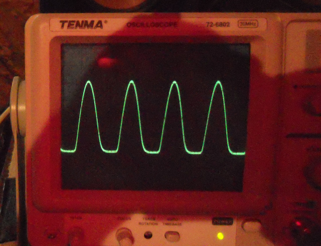
The output to the second stage becomes the inverse:-
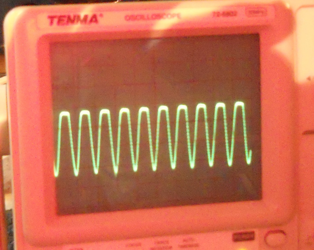
This gets rectified to -ve DC depending on the input level and threshold from zero to as much as -20V.
best
DaveP
 
Usually you connect the attack before the release.
But this has the disadvantage that the attack setting will influence the threshold, because you create a voltage divider. I once reversed these controls; first release and then attack.
In this case the controls don't influence each other much, because the attack resistors are usually (much) smaller than the release resistors.
Something else I usually do is to use two time constants, a small capacitor and a bigger capacitor in series with a resistor in parallel with the small capacitor. The effect is that for short peaks you get a fast release (the bigger capacitor is not charged yet), but for signals with a longer duration, the bigger capacitor will also be charged resulting in a slower release.
I found that this approach makes a compressor sounding more 'musical' (if that is a correct term here...)
Also known as 'program dependent release', 'composite release' or 'auto release'

Following your development with interest!
 
Last edited:
Usually you connect the attack before the release.
But this has the disadvantage that the attack setting will influence the threshold, because you create a voltage divider. I once reversed these controls; first release and then attack.
In this case the controls don't influence each other much, because the attack resistors are usually (much) smaller than the release resistors.
Something else I usually do is to use two time constants, a small capacitor and a bigger capacitor in series with a bigger capacitor in parallel with the small capacitor. The effect is that for short peaks you get a fast release (the bigger capacitor is not charged yet), but for signals with a longer duration, the bigger capacitor will also be charged resulting in a slower release.
I found that this approach makes a compressor sounding more 'musical' (if that is a correct term here...)
Also known as 'program dependent release', 'composite release' or 'auto release'

Following your development with interest!
Ala RCA BA-6B.
 
Something else I usually do is to use two time constants, a small capacitor and a bigger capacitor in series with a bigger capacitor in parallel with the small capacitor.
Interesting.

Sorry for getting off topic/hijacking, what would a good ratio between those cap values be?
 
I usually try different values and keep the one that sounds 'best'.
In a compressor that I have built I used 0.47µF in parallel with 100K + 4.7 µF.
But I think it will depend a lot on the structure of the compressor itself. (And the kind of program material of course...)
 
I have made a few adjustments to improve the performance of the side chain.

The input to either channel needs to be about 0dB or 1.25V, this gives sufficient drive to the side-chain to generate the required negative voltage for compression. With a sine wave input to both channels of the mixbus you get a train of pulses going into the first stage of the side-chain amp:-

The output to the second stage becomes the inverse:-

This gets rectified to -ve DC depending on the input level and threshold from zero to as much as -20V.
best
DaveP


Cool, what the output?
CV?

Would it be replicateble with transistors rather than tubes?
Just a couple of days ago, i was watching a German company that sells transformers, BLOCK and some other ring core manufacturer, but just the "standard" voltages.
270V!!!
 
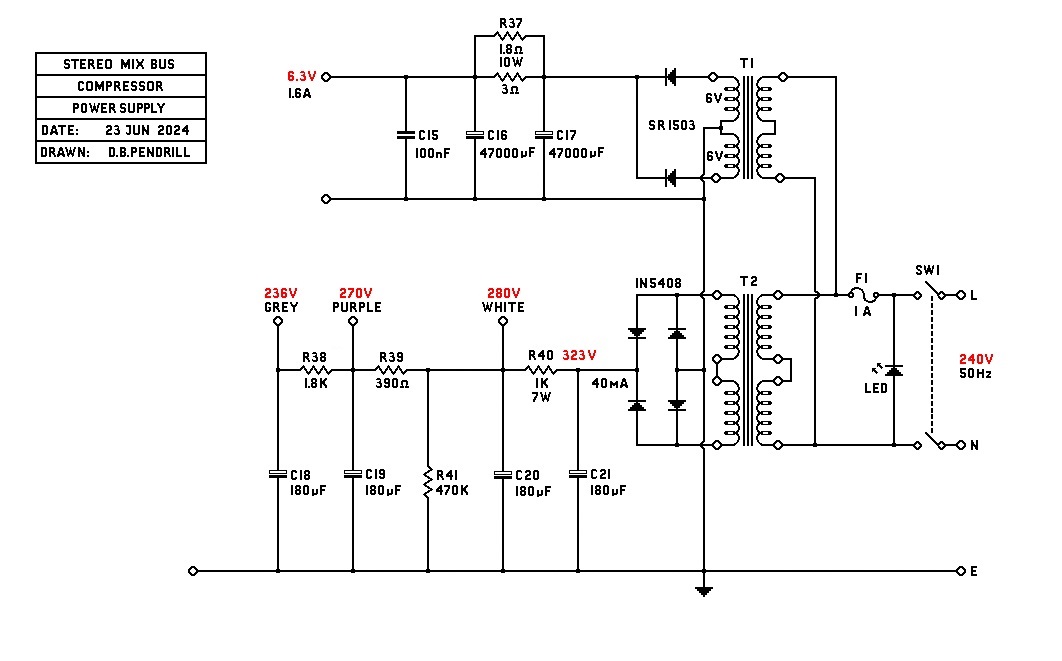
The output is the negative Control Voltage CV to the grid resistors of the input tubes.
I don't see why the side-chain could not be made with transistors if you like, but I prefer working with tubes myself.
The power supply is made with Standard Transformers. B+ is 2x115/2x115, heaters are 2x6/2x115.


cool, discovered the thread today, must read it as whole.

I know the rectified 220V is some 320V.
But i don't like burning watt in to heat, i watch some or quite a few video's on EMC, common and differential noise.
Than i started wondering if you where possible to make a switching psu to generate 270 volt, since most of the video's on EMC was about switching psu's. i have a few little yellow transformers from sourced from broken USB chargers, but lack optocouplers and so.

A compressor is MUST have along Akai MPC, drum computer, synths.

by the way are the diode's in the left/right part of the "side-chain" circuit not a bad thing?
Or is there something else going on? you need a precision opamp wave rectifier (Fallstad - example circuit).
 
Best to read the whole thread first. This compressor will only give around 6dB which will be fine for its intended use for the mix bus. You sound like you might need more than that and there are better designs out there than this.
With a simple power supply all you have to worry about is 50Hz and a few harmonics. Switch mode power supplies are only for the brave.
Best
DaveP
 
Best to read the whole thread first. This compressor will only give around 6dB which will be fine for its intended use for the mix bus. You sound like you might need more than that and there are better designs out there than this.

I could copy them, like a Chinese if it wasn't it for these transformers and weird voltages, big resistors.
But i really don't want to use power resistors for this.

With a simple power supply all you have to worry about is 50Hz and a few harmonics. Switch mode power supplies are only for the brave.
Best
DaveP

Ya, i don't have a spectrum analyzer, something fundamental to get it right, i guess.
For me the most difficult part is the inductor (henry), now someone gave me salvaged parts, but don't know their value.
So you don't play around with more so common than Ohm's law and a bit more.

I really really wanna build the "side chain" of the Teletronix La-a2.
But with a efficient psu, the schematics seem simple.
If you check mouser, you'll see that there many many of these little yellow transformers.
You give up, because you don't know where to start, LOL.

Some time I came with a schematic, circuits to achieve the same.
But these pcb's have, not been made yet.
 

Latest posts

Back
Top