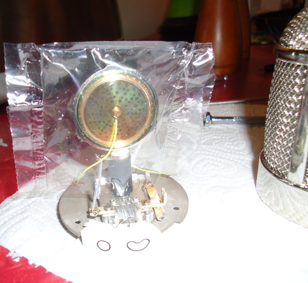
Quote from: grantlack on November 13, 2011, 06:58:52 pm
as i look at the u48 schematic, it appears that the fig8 pattern was accomplished by simply switching a 1nF cap into the signal path between the membranes. any reason the same approach couldn't be taken in the mk47? the execution would be simple enough, it's just a matter of whether it would behave the same. i tend to find omni to be less useful in my day-to-day work.
If your plan is to make a MK48 (sacrifice the omni patern to favor a figure 8 ) it's doable.
Pay attention to the U48 schematic. It's not just a matter of adding a cap and a resistor, you also need to modify the voltage divider.
In the U47 the 2M/3M extract 60V from the 105V PSU in order to polarize the front of the capsule. If you'd polarize the back with 105V, you wouldn't get a real figure 8 pattern (cause you'd need 120V). So for the U48 they changed the voltage divider to 3M/3M. That gives 52.5V to the front, and then 105V at the back is right.
You can do the same with the MK47. Just keep in mind that, just like with a real U48, you'll loose a bit of sensitivity because of the lower polarization voltage.
Axel


