My first tube project help thread (NYD one bottle)

GroupDIY Audio Forum

Help Support GroupDIY Audio Forum:

This site may earn a commission from merchant affiliate links, including eBay, Amazon, and others.
Hey all,

I am having some trouble with a NYD one bottle.

Here is what I have tried:
I grounded the outside of the input transformer which did lower the buzzing. This was not necessary on the other channel. The L channel is totally clean.
I have moved my transformers around (this did nothing)
I changed the wire on the pot to shielded redco 3 line (this did nothing)
I have bypassed my heater traces on the PCB with wires. This was done on the prototype board, not on this one. the prototype also had a buzz in this channel (this did nothing on the proto).
note, on the printed test run of these boards, they are doubled on the PCB, AKA 2 pres per board
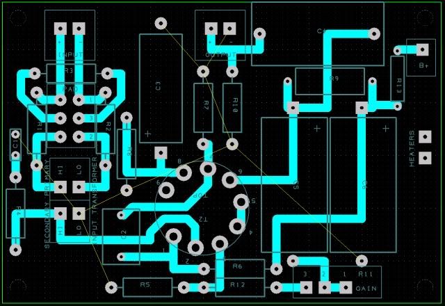
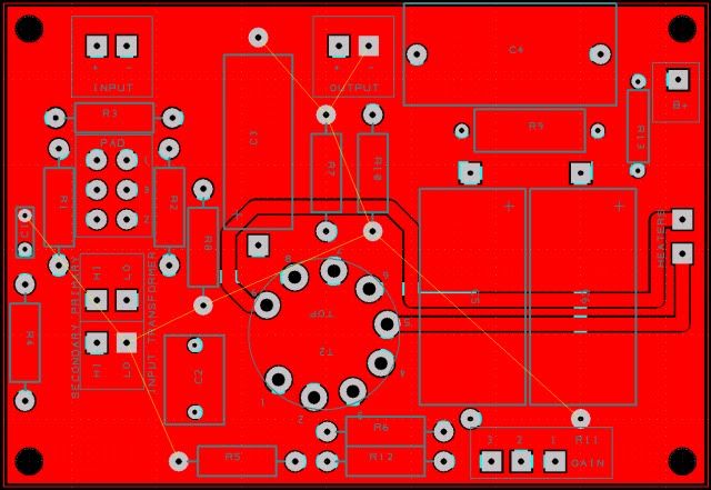
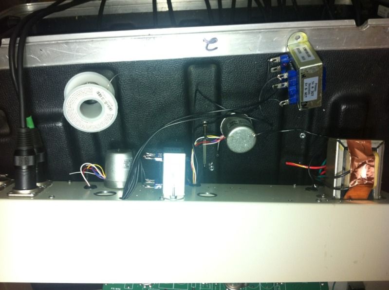
Here is the layout:
bottomcopper.jpg

topcopper.jpg


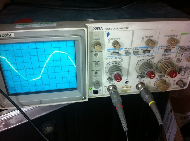
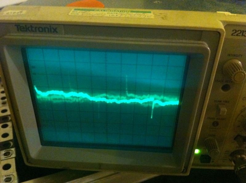
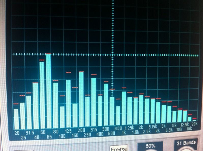
Here is what the AC for the heaters looks like coming in from the power xfrmr (scope is at 2v per division):
feb9d069.jpg


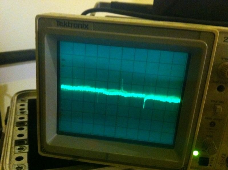
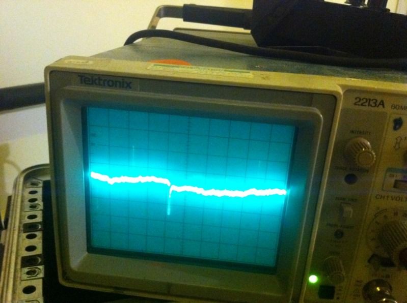
Here is my audio at R12 (scope set to 50m):
c23c9b21.jpg


Here is my audio at pin 2 of the gain pot (scope set to 10m):
cd5b00fc.jpg


Here is my audio at the output coupling capacitor (scope set to 10m):
d7727a0d.jpg


The signal looks like clean dc from the 300V mains supply rail.
There is no buzzing or distortion on pin 7 of the pentode.
It starts post the R12 and works its way to the output cap and then through the transformer.
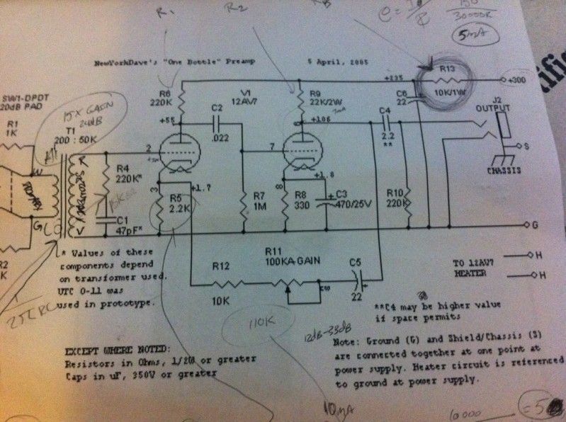
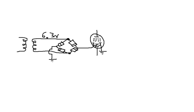
Here is the schemo:
e5668e70-1.jpg


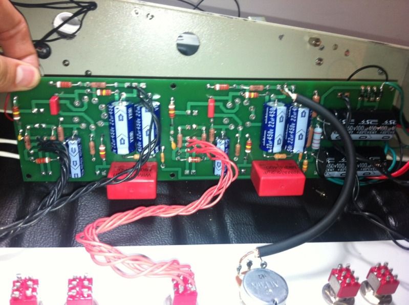
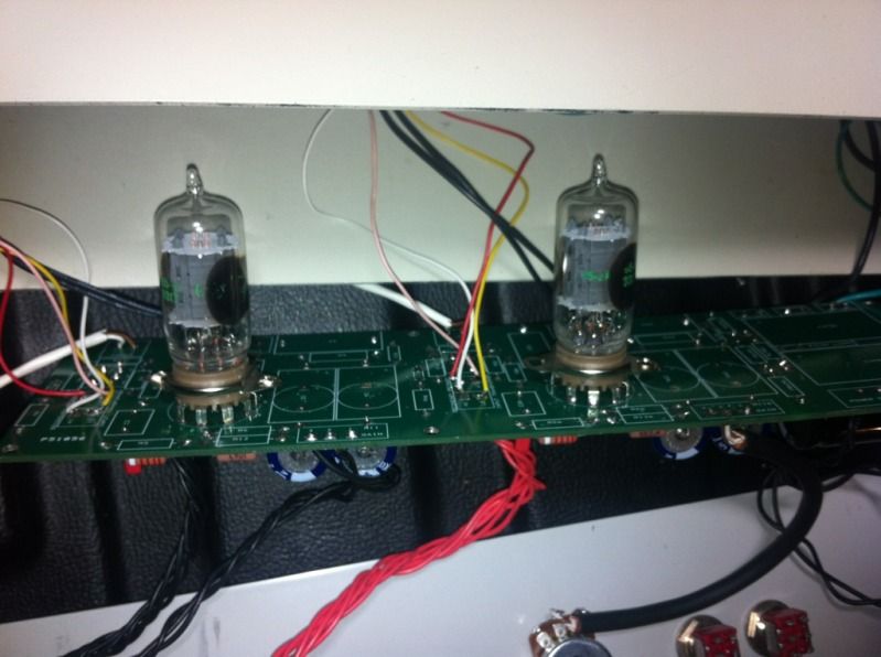
Here are some build pics:
c58263de.jpg

a611e331.jpg

65d00edc.jpg


Here are some pics (please excuse the messy wiring, I plan to clean it up).

Thanks in advance and regardless
 
Description reads backwards from the way I think of it. 
Clean signal at grid 2 if I understand. 
R5 is after R12, R12 is after R11 gain pot. 
Sounds like problem manifests at or after plate 2. 
Most likely seems PT interference with output transformer, and reflected noise back into circuit traceable with scope. 
I'd be inclined to put the audio iron inside the case, with PT outside, or vice versa.  That output is totally unshielded, and most modern inputs are less shielded than vintage iron, so following old style layouts can get you in trouble. 
 
Description reads backwards from the way I think of it. 
Clean signal at grid 2 if I understand. 


Yep, pin two is clean aka no distortion. There is a mic connected but no sound source besides the room sound, which is clearly not the buzzing.

R5 is after R12, R12 is after R11 gain pot.

The junction of R5, does not seem to have the strange peaks. I could look deeper, though.

Most likely seems PT interference with output transformer, and reflected noise back into circuit traceable with scope.

So you believe that it's likely to be the output transformer.. 

I'd be inclined to put the audio iron inside the case, with PT outside, or vice versa.  That output is totally unshielded, and most modern inputs are less shielded than vintage iron, so following old style layouts can get you in trouble.

I mean, I've moved the output transformer around a bit.. It did not seem to help.

I'll smack the PT inside and see what happens.
 
If its Hum it has to be coming from somewhere, either radiating from a power transformer, or from a dirty power supply/ground. DO you know if it is 60hz or 120hz hum? if its 60hz most likely coming from power transformer, if its 120hz most likely coming from the rectifier diodes, which would be from the power supply...

Also How are you grounding the board, and in/out connections? Connecting the audio ground and Chassis ground at one part right? I've found what usually works best for me is connection all the pin 1's of the XLRs directly to chassis and then using only one input xlr to run back to the PCB ground.

Anyway hope this helps!
 
"or from a dirty power supply/ground"

interesting... wouldnt that upset the L channel too? because right now the L channel is clean and the R channel is giving me the crap.

Its not a hum.. its more a buzz. I wish that I had a spectrum analyzer. Maybe there is one built into cubase 5?
 
yea strange. could be a ground loop. or bad tube? do you have a PC? than try the free rightmark audio analyzer. it will show you what the noise floor looks like.

Also is the L or R channel closest to the power diodes/caps?
 
abechap024 said:
yea strange. could be a ground loop. or bad tube? do you have a PC? than try the free rightmark audio analyzer. it will show you what the noise floor looks like.

Also is the L or R channel closest to the power diodes/caps?

Great advice. I will try the rightmark analyzer soon and I will post a shot of it.
 
I was reading a BA-2 Q&A thread and I came across this:

letterbeacon said:
How effective is elevating the 6.3VAC to reduce the hum?  On this page: http://www.freewebs.com/valvewizard/heater.html they mention adding a DC reference by using a voltage divider on the B+ to get between 50VDC and 90VDC and then add that to the 6.3VAC CT.

heater5.jpg

My HT is about 326VDC.  If I make R1 180k and R2 50k that should give me 70VDC.  I'll try connecting that to the CT to see where that gets me.

Does anyone have any experience of this?

I think the conversation past this lead to letterbeacon attempting to add 2 100 ohm resistors to ground coming from the heaters as an attempt to reduce noise..

I'm thinking that if I have low quality AC coming in that it could be causing some noise.

Is this a good and safe idea to try as a noise reduction method?

I'm also wondering, has anyone ever tried adding a smoothing cap in their AC heater lines?
 
Your going to want rectifying diodes if you want to add smoothing caps. Also g for DC heaters, that way no chance of hum entering.
 
okay, its definitely a 63hz hum
babb92c4.jpg


heres what im going to try to get rid of it now.. oh wait, with a cap between it.. but what size..
Untitled-2.png


I guess the DC cant get through the pilot light?
 
buildafriend said:
okay, its definitely a 63hz hum
babb92c4.jpg


heres what im going to try to get rid of it now.. oh wait, with a cap between it.. but what size..
Untitled-2.png


What is relative level of the 63Hz hum?  It looks to be in fair proportion to rest of noise floor.  I find it common to see 60Hz hum at -70db with AC heaters.

You can always use a 100-300r pot for adjustment.  I find this works very well with 4 or less tubes running on same filament string.

There's also the matter of the tubes themselves - some show more residual hum than others.  You will likely see different levels for different tubes. Pull and sort time for that case.

 
If you guys don't mind me asking; how can one measure the amount of noise coming in? what is displayed is an SM57 on the input with the pre cranked to max gain.

I want this thing working so bad! the good channel is so rich and clean.. when I crank the far channel from this one I do not get any hum and I tried switching tubes, transformers, twisting the appropriate wires.. I'm starting to run out of ideas.

I threw in the rectified bridge with a 47uF 25v electro cap and intentionally shorted the pilot lamp. What I got was absolutely no response.. the heaters are not lighting up at all.

now im wondering if it could be too heavy of a diode drop? -0.7v + -0.7v = -1.4v from both of 1n4007's..

I have the direction of my cap correct. in the direction of hot to cold.. the cap is 47uF.. Am I missing a ground connection somewhere? .. I'm thinking as hard as I can..

You guys are the best, thanks so much for the help. 
 
gemini86 said:
PSS

read up.

http://valvewizard.co.uk/

There's a pretty good starting point, which helped me when I first dove into guitar amps (basically the same with some minor differences which you will learn about as you go)

Learn the different topology, what they're good for, benifits, limitations, etc. When you learn them well, you'll see that the NYD 1B is two triode plate output voltage gain stages with variable negative feedback to control the overall gain.

Use this site to look up very basic tube data:

http://www.nj7p.org/Tube.php

Just punch in 12av7 and compare to a 12ax7, 12au7, etc... specifically, note the max power dissipation rating for each type... preamp (voltage gain) tubes have low power dissipation, power tubes (output stages) have more, but less voltage gain.

Good luck! and don't fry yourself! always keep one hand in your back pocket when you're working around tube voltages... that way it's less likely to travel through your heart... Just a quick zapppp....

This seems like helpful information..

http://www.freewebs.com/valvewizard/heater.html

I just came to the realization that I have 20VDC post my bridge.. but 0VDC post my cap.. Hmm 
 
If you guys don't mind me asking; how can one measure the amount of noise coming in? what is displayed is an SM57 on the input with the pre cranked to max gain.

That's a no-no.  You're picking up wind noise and all kinds of random subsonics.

You want to terminate the input with a suitable resistor - 150r, 250r etc - whatever your input iron primary is rated for.

If you already have an input pad wired in, just switch that on.  That will do same basic thing as single resistor.
 
lassoharp said:
If you guys don't mind me asking; how can one measure the amount of noise coming in? what is displayed is an SM57 on the input with the pre cranked to max gain.

That's a no-no.  You're picking up wind noise and all kinds of random subsonics.

You want to terminate the input with a suitable resistor - 150r, 250r etc - whatever your input iron primary is rated for.

If you already have an input pad wired in, just switch that on.  That will do same basic thing as single resistor.

There is already a pad built into the circuit, I'll engage it from now on while doing testing to try to avoid any kind of room noise. Thanks!

When I give the pre a minute to power off, I still get sound which I expected. I also can still hear myself for about 30 seconds.. WITHOUT HUM.

I've added opposing diodes to drop the voltage 0.7 to get less radiation hopefully.

now im adding resistors on the heater traces to ground.. 80ohms on each side. I dont have 100ohm resistors so im using 2 40ohm resistors in series on each side.
 
When I give the pre a minute to power off, I still get sound which I expected. I also can still hear myself for about 30 seconds.. WITHOUT HUM.

Aha, that might be a clue.  Do the reverse test - pay close attention to what happens immediately after you flip the power switch.  Is the hum instantaneous?  Or does it only appear after the tubes start conducting current?  (about 9 sec later).

If instantaneous you might be dealing with PT leakage into something. . .
 
lassoharp said:
When I give the pre a minute to power off, I still get sound which I expected. I also can still hear myself for about 30 seconds.. WITHOUT HUM.

Aha, that might be a clue.  Do the reverse test - pay close attention to what happens immediately after you flip the power switch.  Is the hum instantaneous?  Or does it only appear after the tubes start conducting current?  (about 9 sec later).

If instantaneous you might be dealing with PT leakage into something. . .

oh RLY!  ;D

lets see..


Latest posts

Back
Top