My first tube project help thread (NYD one bottle)

GroupDIY Audio Forum

Help Support GroupDIY Audio Forum:

This site may earn a commission from merchant affiliate links, including eBay, Amazon, and others.
There's a band in pre-pro right now, right behind me. I can check in a few min. If I remember right the hum starts as the tubes heat up. It was not instant.

Edit: Yep just tested it. It starts buzzing once the tubes heat up.
 
Have you tried isolating which stage it originates?  If this is NYD OneBot you will have to open it up and use a clip to ground the grids since their is no interstage volume control.

Well, at least you ruled out certain types of PT leakage.
 
buildafriend said:
Please excuse my being a newbie.

If I ground the grids, it can help to isolate the problem?


Yes.  Start with "V2" (2nd half of the 12AV7).  If it goes away you know the hum is upstream.  Work your way back to 1st tube grid.

It would be helpful if you gave the relative 60Hz hum level you get with the input pad engaged.  How high is it ? - -40db, -60db, -70db etc

 
lassoharp said:
buildafriend said:
Please excuse my being a newbie.

If I ground the grids, it can help to isolate the problem?


Yes.  Start with "V2" (2nd half of the 12AV7).  If it goes away you know the hum is upstream.  Work your way back to 1st tube grid.

It would be helpful if you gave the relative 60Hz hum level you get with the input pad engaged.  How high is it ? - -40db, -60db, -70db etc

Okay, I'll research and learn a method of measuring hum. After I complete measuring the hum I will start with grounding the grids to see where the hum is coming from.

Thanks so much!!!  :) (I'll probably get around to this on Thursday)
 
Okay, I'll research and learn a method of measuring hum. After I complete measuring the hum I will start with grounding the grids to see where the hum is coming from.

Thanks so much!!!  (I'll probably get around to this on Thursday)


Glad to help!  All you need to do for measuring basic hum is to look at the levels on your computer meter screen like the one you posted earlier.  Most of those metering plug ins have a range select.  Set it for as wide as possible (70db or greater).
 
If I was reading things correctly, I was at -70.

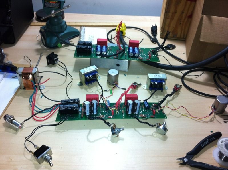
I tried transferring to a new PCB with new components to see if it's a component issue:

DA672B1B-C2BF-4C4C-BE3E-752EB9808F51-893-0000010FB265334A.jpg


I'll get around to testing it again tomorrow night!
 
If I was reading things correctly, I was at -70.

Ok, that puts things in perspective.  If the only noise you have is 60Hz hum at -70 I'd say you are in pretty good shape - in other words you don't have a hum problem.  For AC heaters this is in the realm of normal.  Wiring in a balance pot for the heaters should give you the ability to trim this down towards -80.  If it won't reduce in level with balance pot you will have to try swapping tubes. My ear can't detect hum at -70, at least not as anything objectionable.  Anything much higher starts to become a problem.

You can try taking chopstick and moving filament wires around but I doubt it will make any difference at that low level.


*** In case there is significant noise showing up at other frequencies you may want to do a screen capture that shows the level numbers.
 
Hm, if 70 is usable then I feel like I must not be reading or measuring correctly. It is definitely not usable to normal standards.

One channel is so clean compared to the other.. The clean on is usable. I'll work on making sure that I am getting an accurate reading.

Thanks!

 
That's why I also asked if you could do a full screen capture of the noise profile.  There may be other noise types in there being caused by other things.
 
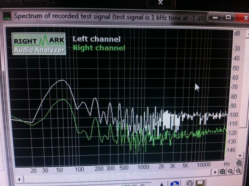
White represents the channel that is mounted on the PCB closer to the PSU caps, green represents the pre that is clean.. I tried moving all parts around and shielding the left side with some alloy. Both channels were cranked with the pads engaged.
9E4B8390-A621-446E-B55A-0251E784724B-1402-0000020F56E1AF3A.jpg


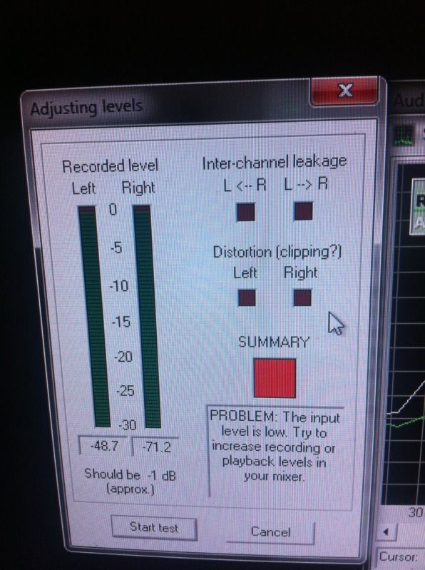
But it also read this, I assume that I should be ignoring it as the readout on the analyzer seems as if it would be accurate.
890DC00D-F8AE-4F7C-9C9E-B9E2E1457D46-1402-0000020F794586F1.jpg
 
Ok.  Your noisy channel is up to -60 which is not so good. 

Is the PT inside the case as well?  It was hard to tell how the final build was layed out from the earlier pics

I'm not sure which one is most accurate.  You can hear -60 and -48.7 would be even worse.  Either one should work fine as a reference as you try different things.

So, so far you have rebuilt on a new PCB, rotated input and output and none helped?  Did adding the alloy help, even by a small amount?

You mentioned seeing it around R12.  Try grounding 1st tube half grid (pin2) and see what happens to hum level.  If the input transformer is picking up majority of hum, then grounding this grid should show a big reduction in hum level.  If it changes nothing then go to 2nd grid (pin 7) and ground.


On the last/most recent picture of the rightmark scan, I had one gain pot wired backwards so the -80dB channel should have actually looked matched to the -60dB channel.

Both channels are at -60dB and both channels are at full gain with pad engaged.

They are both currently not in the chassis as show in this picture:
DA672B1B-C2BF-4C4C-BE3E-752EB9808F51-893-0000010FB265334A.jpg


When I grounded the first grid(pin2), It took me down to -80dB

When I grounded the second grid(pin7), it took me down to -70dB

Since both channels are now at the same barely usable -60dB level while outside of the chassis, is it safe to assume that the issue was in a component and that the chassis should quiet things down enough?

There is only one way to find out. I'm throwing it back in.
 
Since both channels are now at the same barely usable -60dB level while outside of the chassis, is it safe to assume that the issue was in a component and that the chassis should quiet things down enough?


That's reasonable but >>before you do that<<  you have an opportunity for a very simple test which will not be easy to do in chassis -

Move both (but do one at a time for differentiation) input and output iron towards and away from the PT and see what the hum level does.  It should increase as you go closer to PT and fade as you move away.  Also use this out of chassis set up to find the best null position for input and output.

From your grid grounding test I'd say you're picking up a certain amount of hum from the input.

Being out of chassis it easy to pick up stray RF garbage but I'd do the proximity test with PT.  At the very least you will have learned exactly where the nulls are and how to best position things inside.


* If Right Mark doesn't allow real time analysis, a quick and easy way for monitoring hum is to run the preamp into a power amp and monitor through a speaker.  Makes it easy to hear where the null falls.  Then sweep while holding transformer in the best null position and see where that lands.
 
I was having a similar problem on one of my OBP's, the exact same problem, in fact. In my case, it was the cable run from the input XLR to the pad switch and back. I had my cables tightly wound but that didn't seem to help. I solved the problem by using shielded cable for that run, making it as absolutely short as possible and grounding the cable shields to the star ground to make a Faraday cage. I did all of that and my noise floor dropped by about 12dB, well within the useable range. I'm not at the studio computer or I'd post rightmark results before and after.

Looking at your layout, I'd bet dimes to doughnuts you are picking up your hum in the cable run to/ from the input transformer or to/from the pad switch.
 
It couldn't hurt to get some shielded cable.. I'll order some. The only kind I have now is redco XLR. It's too bulky for the inside of this project chassis.

I need to plan my chassis drilling better next time for more direct cable to PCB access.
 
I salvaged mine from some unused TRS cables we had lying around. My layout is point to point, but if I had it to do over again, I'd add a relay at the xlr for the pad to save that run.

Oh, and I had to run down one red herring after the changes. I was still getting a LF hum after adding the shielded cable, just a different frequency, turns out it was the crappy window AC unit by my workbench vibrating the wall my bench is hooked to and slightly vibrating what turned out to be a micro phonic tune. Turned off the AC and selected another tube and that fixed that.
 
Are those Sowter input transformers? Looking at your pic, it occurred to me that your problem is actually probably that input iron. Get that outta there and mail it to me for analysis immediately. It will take me several years, but I will most likely be able to tell you if it's useable or not.
 

Latest posts

Back
Top