Neumann M49 Clone : Build Thread Puck Style (TLM49 Conversion To M49 b-c)

GroupDIY Audio Forum

Help Support GroupDIY Audio Forum:

This site may earn a commission from merchant affiliate links, including eBay, Amazon, and others.
Look up the heater voltage and current, use ohms law to get a resistance, and use a power resistor of that value to sub for the tube. It might be right- tube heaters take quite a bit of current.
 
diylan said:
Hey everyone, I'm having some power supply issues and I'm hoping someone can help me out.

My H+ measured without the mic connected is only trimming between 20 - 27vdc! Not wanting to fry the tube, I haven't measured with the mic plugged in. My mains runs a little high (~ 125vac), and I'm measuring ~ 25vac across the transformer secondaries, but that doesn't seem like it would account for such a huge voltage at H+. My B+ also seems to be running high, trimmed to it's lowest point it's around 130 vdc.

Any thoughts?

this is a full Passive Power supply so basically if you have no load to the power supply it will read much higher ,
check this thread for the proper way to test under load and adjust the Voltage,
Best,
Dan,
 
Ball Park figure is <

Heater = 6V at 150ma
B+ 120V at 0.8ma


Heater
U=RI
P=VI
then Test Load = 6V/.150A = 40ohm
then P (watt) = 6V*0.150A = 0.9W then 2 watt will be fine.


B+
U=RI
P=VI
then Test Load = 120V/.0008A =150Kohm
then P (watt) = 120V*0.0008A = 0.096W then 1/4 watt will be fine.


Hope this helps,
Dan
 
Wow, I can't believe I missed it earlier in the thread. Sorry about the redundant question!

All powered up now and everything is working great. Time to see how it sounds. Thanks!
 
8)

this Is Rare to See,  either you buy this or a Car

http://www.ebay.com/itm/Neumann-M249B-pair-with-consecutive-serial-numbers-/201330485060?pt=LH_DefaultDomain_0&hash=item2ee03b6744

Best,
Dan,
 
That looks like a sweet deal, Dan! 

Look at it this way; what is the car worth in 5 or 10 years, and what is a pair of 49:ers worth then?
And think of all the money you can make on your wonderful recordings with them!

So the question is, should I sell my gar and get these..?! 

I think anyone in this thread is playing with the thought..  8)
 
Question for Dany,

I got the BV11 from Max. How do I orient it? Not sure what Pin 1 is, or which way it should go on your lovely round PCB...

Thanks,

Mike
 
Hi Dany, still having trouble. I found a schematic of the BV11 pinout, but it seems to be a mirror image of what your PCB has...am I supposed to mount the BV11 on the opposite side of the silkscreening on the PCB? In other words, use the side silkscreened AMIT49?

In that case, the black dot on my BV11 would match the schematic and would seem to match your traces. If mounted on the reverse side. Have you checked this?

Can you help out? Kinda stuck. Trying to trace the traces visually but it's a bit of a tough go as I'm not an EE.

Thanks,

Mike
 
Question for anyone who built the "b" version - is there anything special about the "high z" section that's different than Dan's pix in the beginning of this build? He's got the "c" version there and I'm a little confused as to where some things go...it seems some values are different and some are not there.

Thanks for any thoughts.

Mike
 
OK I got it stuffed correctly (I think).

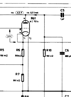
I've got an ac701 I got for a good deal. I wired it in, but my voltages are not what they should be. Dunno if the tube isn't good or if I screwed something up. This is the "b" version.

I've got B+ at 116v and H+ at 3.94v.

Measuring across R10, I get:  116-33 = 83v for a place current of .83mA (tad high).

With ground attached to HG, I get the following:

K = 3.94v (should be 1.6v)
A = 33.8v (should be 43v)
H+ = 3.92v (correct)

Between H+ and FGRID I get .65v. Between HG and FGRID I get .27v.

Turning trimmer R7 doesn't seem to do anything for any of the voltages above.

Scratching my head and would appreciate any input. Need to get this sorted.

Thanks,

Mike

EDIT: I should probably mention I left out C6 and R3, and set C4 to 2pF. No capsule installed and no dummy cap in place of the capsule.
 
Phrazemaster said:
OK I got it stuffed correctly (I think).

I've got an ac701 I got for a good deal. I wired it in, but my voltages are not what they should be. Dunno if the tube isn't good or if I screwed something up. This is the "b" version.

I've got B+ at 116v and H+ at 3.94v.

Measuring across R10, I get:  116-33 = 83v for a place current of .83mA (tad high).

With ground attached to HG, I get the following:

K = 3.94v (should be 1.6v)
A = 33.8v (should be 43v)
H+ = 3.92v (correct)

Turning trimmer R7 doesn't seem to do anything for any of the voltages above.

Scratching my head and would appreciate any input. Need to get this sorted.

Thanks,

Mike

EDIT: I should probably mention I left out C6 and R3, and set C4 to 2pF.

Measuring at K direclty wont give you the 1.6V it is the difference between the Grid and the filament voltage look closely to schemo  , do you have a 2M tweaking pot or a 5K pot there ? 2M should be for the 49b, IIRC it says so looking in the BOM note from mouser Bom
(Grid(V)-K(V)) , but not if you measure K direclty , because you only read the filament voltage a this location  ;),
Let me know if this make sense ,  try tweak and check back other parameter. once you get there you can try subing the 100K plate resistor for something like 150K instead of 100K , but in term you should be able to get without that modification

hope this helps,
Best
Dan,


Hi Dan, thanks much for the response. It's a 2M.

I wonder if it's a bad pot; twisting it does nothing.

Suggest I replace it, or sub in a 100k resistor since I'm using an ac701?

Thanks,

Mike
 
Phrazemaster said:
Hi Dan, thanks much for the response. It's a 2M.

I wonder if it's a bad pot; twisting it does nothing.

Suggest I replace it, or sub in a 100k resistor since I'm using an ac701?

Thanks,

Mike

what i am saying is you have to measure the Voltage difference between Grid and heater voltage to get the bias (1.6V) reading if you DMM has the right impedance to do it ,  R7 should be equal to 300K in the 49b and R10 100K ,
you can try to fit R7 first , 100K should be the righ plate resistance for this one as well,

look here :
58d0281994650.jpg


Let me know,
Best,
Dan,

 
Thanks Dan. I replaced the R7 trimmer; apparently it was bad. However, I'm still only getting about .5v bias across FGRID and the H+. If I read the schematic right, that's the correct place to measure, right?

If I measure from FGRID to HG, it's about 1.9v.

Turning the trimmer doesn't change the plate voltage, which now is about 27v.

I'm wondering if this could just be a bad tube?

What would make the voltage across R10 so low, and why won't the trimmer affect it?

Thanks any other thoughts; you're the best.

Mike
 
Phrazemaster said:
Thanks Dan. I replaced the R7 trimmer; apparently it was bad. However, I'm still only getting about .5v bias across FGRID and the H+. If I read the schematic right, that's the correct place to measure, right?

If I measure from FGRID to HG, it's about 1.9v.

Turning the trimmer doesn't change the plate voltage, which now is about 27v.

I'm wondering if this could just be a bad tube?

What would make the voltage across R10 so low, and why won't the trimmer affect it?

Thanks any other thoughts; you're the best.

Mike

your meter may not allow to measure form this high impedance source ,
so try to aim your plate voltage the same way varying this resistor R7 and then you should have the bias pretty close ,
at least from experience when the plate voltage is right the rest follows as well since you have the same tube it should line up with it,
hope this helps,
Best,
Dan,
 
OK I measured from FGRID to HG - got 1.6v - I think that's the wrong place to measure.

No amount of turning R7 pot changes the plate voltage. The trimmer is still good, as I checked it from the bottom of the PCB and the values change as I turn the screw.

Still only getting 28v across R10...

EDIT: added a pot in parallel to R10, and a value of about 45K makes plate voltage ~43v. I guess I'll strap a little parallel resistor onto R10 then of about 45K or so? Have to figure the maths for current...

OK that won't work; total R is roughly 31K giving very low current.

And I still I do not get right voltage on bias; about 0.5v. I have a Fluke 87 True RMS meter so I'm not sure how it's getting fooled if it is...

Any other thoughts Dan?

Could the tube be bad per se?

Thanks,

Mike

Thanks!
 

Attachments

  • puck.jpg
    puck.jpg
    299.8 KB
Still working on this...

I replaced R10 with a trimpot and with a value of 41K, and using 120V for B+, I get 43v at plate, as per schematic value.

But then the current is too high:

120-43=77V across R10.

V=IR

I=77V/41000 = 1.9mA

This is more than double the specs. I don't want to fry her royal highness.

With using a 100K resistor at R10 as specified, I only get 28V across it, which gives me: 116v-28v=88v across R10, for a current of .88mA - closer to spec but still a bit high.

Again, trimpot R7 does not affect the plate voltage at all for some reason.

I'm seriously thinking of stuffing the "c" version now, or perhaps swapping this tube with a 5840 that I have in ample supply.

Can anyone make any suggestions? I'm stuck.

Thank-you,

Mike
 
Well I guess the "technical angels" have come to my rescue!

I was trying to figure out if the 2M trimmer was working, or if it was broken - those dang things are so easy to break!

So I flipped my bad boy over and tried measuring from the bottom left two points under the pcb - the resistance varied from about 182K at the 2M position, to 0. So I knew the trimmer was working, but I realized you can't tell the right value of the trimmer with it installed. I wanted to set it to 300k per schematic. Problem was, it was a bear removing the last one, and the pcbs gets nasty after too many lifts of components.

So I used maths. I said, "the whole mic has got to be a parallel resistance with this trimmer. Let me discover the whole mic resistance."

I used 1/Rtot = 1/R1 + 1/R2

1/182K=1/Trimmer Tot (2M) + 1/R2

R2 came to 200.2K, representing the rest of the mic total resistance in series with the pot.

Armed with this, I then calculated what the trimmer would need to be to set it to 300K:

1/R? = 1/200.2K + 1/300K

R? = 120K, which represented the value the trimmer needed to measure to be set internally to 300K.

So I screwed it down to 120K and then took measurements...

OMG!

43v over the plate! Using 100k resistor, 72.5mA current!

I had used a trimpot for the 100K earlier, and had decided to set it to exactly 100K and did so. Since it worked, I replaced the pot with a 100K resistor, and I'm still getting the right values!

My guess is, the R7 trimmer is very susceptible to the IPA and the flux remover; perhaps the values it was putting out for R7 before were screwed up - because I didn't change anything! I guess simply waiting a few hours did the trick...

Anyway, I'll report back after I get the capsule in and...do the first audio test!

Thanks for your patience guys!

Mike
 

Latest posts

Back
Top