Neumann M49 Clone : Build Thread Puck Style (TLM49 Conversion To M49 b-c)

GroupDIY Audio Forum

Help Support GroupDIY Audio Forum:

This site may earn a commission from merchant affiliate links, including eBay, Amazon, and others.
This is a PSU question, probably for Dany but for anyone who wants to chime in with expertise.

I'm going to put a delay-start board into the mic PSU to delay the heater for about 30 seconds. It's a cool little board, but it requires about 6VAC to run it. Also takes 200mA.

I was going to use the center tap of the H+ transformer to get about 10V and then drop it down a bit with a resistor.

My concern is that the M49 H+ takes ~100mA alone, and this delayed start circuit takes another 200mA. The transformer is rated at 300mA. Isn't this pushing it? I'll be taking the power in parallel, so A is added for parallel circuits. But still...

Will this B+ transformer be powerful enough to run both the mic H+ as well as the delay-start board? I'm not knowledgeable enough in electronics to know if this is fine, or a risk.

Any thoughts are welcome. Thank-you.

PS the delay-start board is here: http://www.kandkaudio.com/other-kits/

Scroll down to find the board.

Thanks
 
I have a question regarding the Hammond Euro xformer. I am setting up my PSU for dual voltage, with a voltage selector switch. I'm fine with the primary winding, using a voltage selector switch that handles the series or parallel configurations for the primary winding.

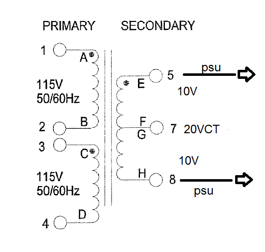
I'm a little confused about the secondary, however. Which output do we use for 20V for USA, and which output to use for European use to get the 20V? Dan's PSU schematic shows 20V and the Hammond Datasheet shows a 10V center tap and two 5V windings...sorry if this is basic.

Also, will I need another voltage selector switch to handle the secondary?

I want to be able to take this PSU to Europe as I'm moving to England in a few months, and I want the dual-voltage capability.

Thank-you,

Mike
 
Phrazemaster said:
I have a question regarding the Hammond Euro xformer. I am setting up my PSU for dual voltage, with a voltage selector switch. I'm fine with the primary winding, using a voltage selector switch that handles the series or parallel configurations for the primary winding.

I'm a little confused about the secondary, however. Which output do we use for 20V for USA, and which output to use for European use to get the 20V? Dan's PSU schematic shows 20V and the Hammond Datasheet shows a 10V center tap and two 5V windings...sorry if this is basic.

Also, will I need another voltage selector switch to handle the secondary?

I want to be able to take this PSU to Europe as I'm moving to England in a few months, and I want the dual-voltage capability.

Thank-you,

Mike

only the primary needs to reflect the country ,
the secondary will stay the same , the datasheet also is generic for the hammond transformer ,
so this will probably help you out , this is what it is in the real life

58d028199449d.gif


Best,
Dan,
 
Phrazemaster said:
Thank-you Dan, I suspected as much.

The same thing applies to the toroid transformer as well then, right?

Thank-you much..

Mike

not sure what your asking here ,
let me know,
D
 
The toroid primary can be wired in parallel or in series for 115/230 operation. I've got a dual voltage selector on the primary for that.

The secondary winding can also be wired in series or in parallel. If I understand correctly, I should wire it parallel regardless of how I wire the primary to get 115v output..

Is that correct?

The reason I was confused is when I looked online it said if you wire a transformer in series you get double the voltage for the secondary. I was confused thinking wiring primary in series 230v and not changing the secondary wiring - how you still get 115v out on secondary without changing its wiring?

Thanks; hope that was clear.

Mike
 
The secondary winding can also be wired in series or in parallel. If I understand correctly, I should wire it parallel regardless of how I wire the primary to get 115v output..

Correct ,
DAn,
 
Hi Dan,

I wish to make the B version.

I notice that you bridge a lot of components, even though there is a hole in the PCB.
For the B version, I should completely follow the build pics on the first page?

Thanks
Neil
 
Le Roux said:
Hi Dan,

I wish to make the B version.

I notice that you bridge a lot of components, even though there is a hole in the PCB.
For the B version, I should completely follow the build pics on the first page?

Thanks
Neil

it is almost identical build the stuff shown here for the c version will remain valid for b version as well
if you look at both schematic side to side you will notice that they are only menute difference for tube bias
Best,
Dan, <
 
Hi Dan,

I'm building the M49c version and I have a (beginners) question:
There is an connection 8, "calibration input" on the mic pcb. There is no "calibration output" on the psu pcb. What is the calibration input for and what am I supposed to do with it? What have I missed?

Thanks,
Stefan
 
stelin said:
Hi Dan,

I'm building the M49c version and I have a (beginners) question:
There is an connection 8, "calibration input" on the mic pcb. There is no "calibration output" on the psu pcb. What is the calibration input for and what am I supposed to do with it? What have I missed?

Thanks,
Stefan

Pin 8 calibration can be used direct at the mic pcb to inject tone or sweep for tweaking C4 and R3 feedback for advanced mic builder only,  I recommend the stock value as a starting point for those they are pretty much dead on.
Best,
Dan,
 
I will have a small batch available of those round Version Pcb kit as of next Week,
if interested let me know .
thanks,
Dan,
 
Thank you, Dan.

One more question: I would like to inject a test signal into the mic board (not using a capsule) for adjusting the bias and see if there is any gain difference between different tubes.
I'm building a small faradays cage where I can burn in and test my tubes without having to solder them to the board. 
Can I just connect the signal generator directly to FGRID and HG? Does it matter that the test signal is a low impedance source?

I appreciate your help!

- Stefan


stelin said:
Thank you, Dan.

One more question: I would like to inject a test signal into the mic board (not using a capsule) for adjusting the bias and see if there is any gain difference between different tubes.
I'm building a small faradays cage where I can burn in and test my tubes without having to solder them to the board. 
Can I just connect the signal generator directly to FGRID and HG? Does it matter that the test signal is a low impedance source?

I appreciate your help!

- Stefan

yes you can do that , most of the signal gen are around 50ohm impedance IIRC mine is, so there should not be any issues with that , if you compare apples to apples there is no issues,  if you do that make sure you replace the capsule with a dummy capacitor arround 72pf willbe fine ,
Best,
DAn,

 
Hey everyone, I'm having some power supply issues and I'm hoping someone can help me out.

My H+ measured without the mic connected is only trimming between 20 - 27vdc! Not wanting to fry the tube, I haven't measured with the mic plugged in. My mains runs a little high (~ 125vac), and I'm measuring ~ 25vac across the transformer secondaries, but that doesn't seem like it would account for such a huge voltage at H+. My B+ also seems to be running high, trimmed to it's lowest point it's around 130 vdc.

Any thoughts?
 
Back
Top