Neumann M49 Clone : Build Thread Puck Style (TLM49 Conversion To M49 b-c)

GroupDIY Audio Forum

Help Support GroupDIY Audio Forum:

This site may earn a commission from merchant affiliate links, including eBay, Amazon, and others.
pasarski said:
poctop said:
The only suggestion that come to mind is in the c version with the 5840 the cathode bypass cap specified at 22uf(25uf) can be replaced with a 10uf for better bass response...

You mean 100uF?

Sorry I meant C9 on the c version from 22uf to 10uf ,
best,
DAn,
 
I believe that increasing the value of the bypass capacitor at C9 is what is needed to improve the bass response.
 
poctop said:
pasarski said:
poctop said:
The only suggestion that come to mind is in the c version with the 5840 the cathode bypass cap specified at 22uf(25uf) can be replaced with a 10uf for better bass response...

You mean 100uF?

Sorry I meant C9 on the c version from 22uf to 10uf ,
best,
DAn,

What Meant as Better would have meant a more Linear Bass Response,
Sorry for the confusion ,
Best
Dan,
 
Edward said:
Is the inductor in the PSU connected to X1-1 and X1-2?

There is no polarisation on that inductor, right?

Correct,
Best,
Dan,
 
Thank you for your reply Dan.

I am quite sure i read somewhere about how to make a test load to adjust the PSU before connecting the microphone, but i can't seem to find it. Does anyone know where to find that? My PSU is hooked up and ready to go, not seeing any smoke comming from it yet :)

Also, i swapped pin 3 and pin 7 in the PSU end, is that correct?

Sorry if i am repeating questions.
 
Edward said:
Thank you for your reply Dan.

I am quite sure i read somewhere about how to make a test load to adjust the PSU before connecting the microphone, but i can't seem to find it. Does anyone know where to find that? My PSU is hooked up and ready to go, not seeing any smoke comming from it yet :)

Also, i swapped pin 3 and pin 7 in the PSU end, is that correct?

Sorry if i am repeating questions.

Nop, not at the psu end , at the mic end, 
here is a reminder, 


Cabling connection From PsU https://cdn.groupbuilder.com/groupdiy/u/39511/58d0281993f31.jpg

what you have to remember is that on the mic end pad 3 on pcb is the 0V and the pin 7 is the chassis/sheild

it actually does not matter since pad 3 and pad 7 on the mic pcb is the same but on the psu the pin 3 has the sheild lift function so if you tie this one on the 0V and lift the shlf jumper then you dont have a return ,

so in simple pin 3 from psu goes to pad 7 on pcb and pin 7 of the psu goes pad 3 on the mic pcb.

then if you have a wrong ground scheme you are aware of this distinction.

hope this helps,
Dan,
 
poctop said:
Edward said:
Thank you for your reply Dan.

I am quite sure i read somewhere about how to make a test load to adjust the PSU before connecting the microphone, but i can't seem to find it. Does anyone know where to find that? My PSU is hooked up and ready to go, not seeing any smoke comming from it yet :)

Also, i swapped pin 3 and pin 7 in the PSU end, is that correct?

Sorry if i am repeating questions.

Nop, not at the psu end , at the mic end, 
here is a reminder, 


Cabling connection From PsU https://dl.dropboxusercontent.com/u/43869772/PSU%20cabling%20to%20M49%20and%20M269c.jpg

what you have to remember is that on the mic end pad 3 on pcb is the 0V and the pin 7 is the chassis/sheild

it actually does not matter since pad 3 and pad 7 on the mic pcb is the same but on the psu the pin 3 has the sheild lift function so if you tie this one on the 0V and lift the shlf jumper then you dont have a return ,

so in simple pin 3 from psu goes to pad 7 on pcb and pin 7 of the psu goes pad 3 on the mic pcb.

then if you have a wrong ground scheme you are aware of this distinction.

hope this helps,
Dan,


AH! I'm an idiot.Again. Glad i asked, thank you!

What about that test load? Tried searching and scrolling through some threads but i can't find it...
 
Ball Park figure is <

Heater = 6V at 150ma
B+ 120V at 0.8ma


Heater
U=RI
P=VI
then Test Load = 6V/.150A = 40ohm
then P (watt) = 6V*0.150A = 0.9W then 2 watt will be fine.


B+
U=RI
P=VI
then Test Load = 120V/.0008A =150Kohm
then P (watt) = 120V*0.0008A = 0.096W then 1/4 watt will be fine.


Hope this helps,
Dan
 
Hi quick question Dani; I could swear at one point I saw that the puck will work with Max's BV11 - but I can't find the thread (I have looked!). I just want to make sure; I thought at one point you had said one side was for the AMI xformer and the other for the Max BV11...

Thx, sorry if this was obvious. I actually already bought the BV11 from max but when I went back to try to find the thread for some reason I couldn't.

Mike
 
Phrazemaster said:
Hi quick question Dani; I could swear at one point I saw that the puck will work with Max's BV11 - but I can't find the thread (I have looked!). I just want to make sure; I thought at one point you had said one side was for the AMI xformer and the other for the Max BV11...

Thx, sorry if this was obvious. I actually already bought the BV11 from max but when I went back to try to find the thread for some reason I couldn't.

Mike
OK sorry nevermind; I found the reference...

poctop said:
dissonantstring said:
Does anyone know if Max's BV.11 transformer will 1) work with Dany's xfrmr pcb & 2) also fit in this M49 mic body used on said board?  Thanks!

Hi Grant ,

if you look at post #68 on this thread you will see that the transformer adaptor board has been designed in consequence to have Max transformer on it if you flip the board on on side you have Max transformer and on the other side the AMI T49 it can also be a wired transformer .

WMX.jpg


i havent got a hold of Max or Max transformer yet has it has just came out but it will theoritically pop right in , and has been patched to work...

I am expecting myself to try it out soon enough .....


So it is a theoritical Yes for now, 

Let see what happens,  ;)
Best,

Dan,
 
Hi Poctop,
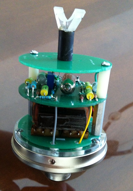
The mouser cart for the mic parts doesn't seem to be complete.
They are missing some parts I think.
The m269 cart is missing a lot as well.
Dan
 
dmp said:
Hi Poctop,
The mouser cart for the mic parts doesn't seem to be complete.
They are missing some parts I think.
The m269 cart is missing a lot as well.
Dan

could you explain a bit ,
LEt me know,
d
 
Sure,
When I load the 49 cart, I don't see the standoffs (I guess that is the only thing missing on the 49)
When I load the m269 cart, the 2n2 Wimas, R4, R7...

Not a big deal - just wondering if the carts got goofed up.
 
dmp said:
Sure,
When I load the 49 cart, I don't see the standoffs (I guess that is the only thing missing on the 49)
When I load the m269 cart, the 2n2 Wimas, R4, R7...

Not a big deal - just wondering if the carts got goofed up.
from the top of my head ,
the M269c should be as this : 
U67 Mic parts + M269 options,

U67 Mic part :        http://www.mouser.com/ProjectManager/ProjectDetail.aspx?AccessID=83ad963d23
M269 b or C option http://www.mouser.com/ProjectManager/ProjectDetail.aspx?AccessID=6bb38c7d28
PSU :                      http://www.mouser.com/ProjectManager/ProjectDetail.aspx?AccessID=532017ac2f

the BOM are read only on my side hence they should never be modified,
Let me know if this helps,
D
 
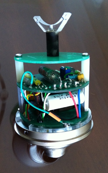
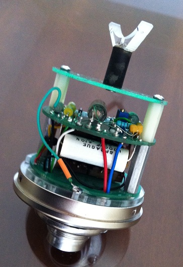
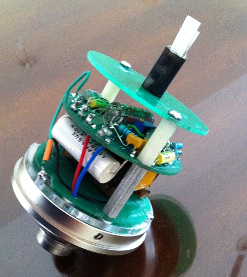
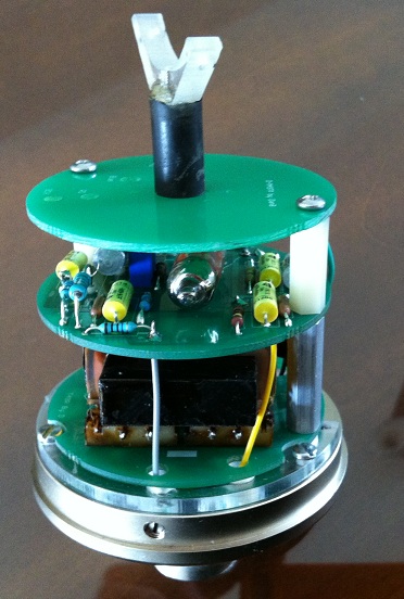
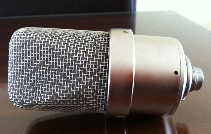
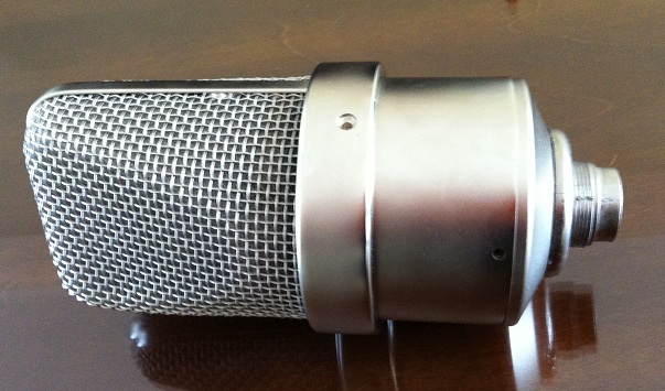
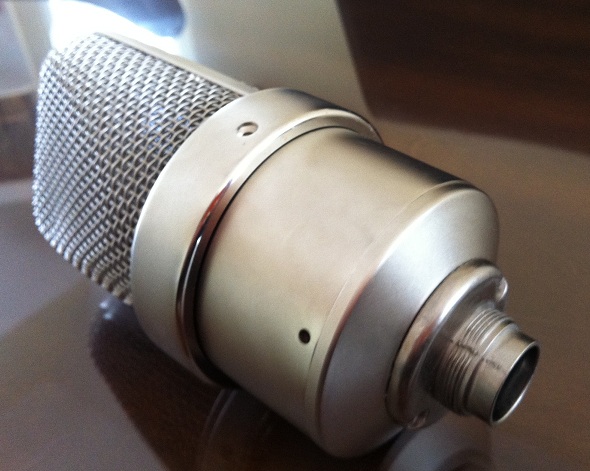
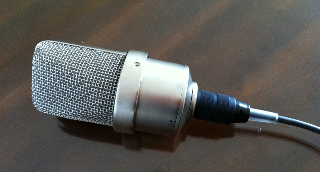
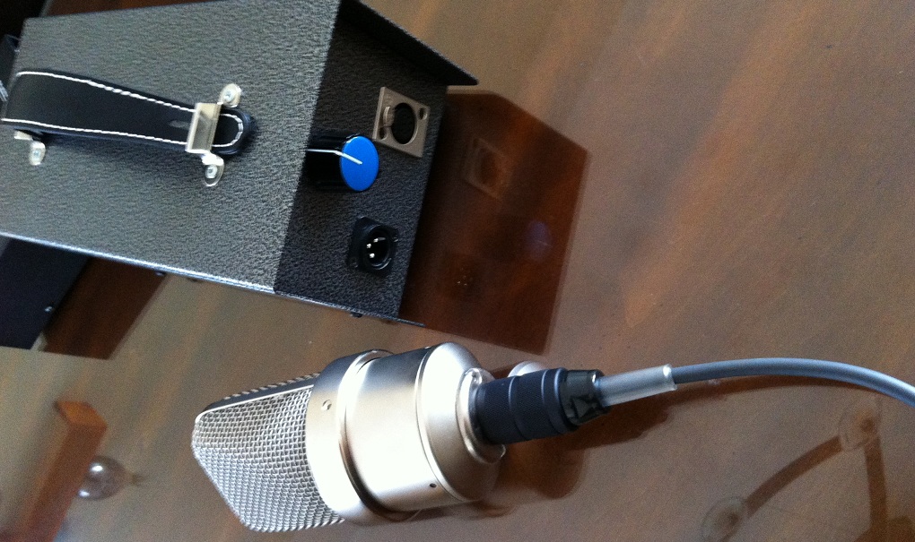
Finally had to finish pending project that have been sitting for a very long while,

D-M49

58d1402a06b23.jpg


58d1402a06b30.jpg


58d1402a06b41.jpg


58d1402a06b52.jpg


58d1402a06b63.jpg


58d1402a06b74.jpg


58d1402a06b85.jpg


58d1402a06b96.jpg


58d1402a02922.jpg


58d028199413b.jpg


Latest posts

Back
Top