Neumann U47FET Clone: D-U47 FET Microphone Project PCB Build thread

GroupDIY Audio Forum

Help Support GroupDIY Audio Forum:

This site may earn a commission from merchant affiliate links, including eBay, Amazon, and others.
Potikinawah said:
Hi Dan,

Just had a question. Is the D-U47 suitable for a multi-pattern U47fet (8-cardio-omni) ? Just need a good microphone capsule and (the difficult stuff) the right body with a 3-position switch on ?

Thanks,
Yoh

the D-U47 FET just like the originals beast is a supercardiod only microphone ,  there is a pad and a low cut but the pad require a dpdt switching device but as usual you can use the internal jumper setting to use them IMO once they are set i use it pretty much on everything without even thinking about it .

Best,
Dan,
 
Leer said:
Does the Sowter transformer fit inside the Alctron-style mic?

Thanks, Peter.

do you have the precise dimension of the sowter transformer i could measure at home,

Let me know ,
Best,
dAN,
 
It's their 1303, cylinder shape
Ratio 9:1. Sowter designed transformer similar to Neumann U1 with a single secondary winding. Internal electrostatic shield to ensure good comon mode rejection.
Mumetal can with colour coded leads 34 mm dia. x 24 high.
from the sowter homepage
Thanks,
Leer.
 
Leer said:
It's their 1303, cylinder shape
Ratio 9:1. Sowter designed transformer similar to Neumann U1 with a single secondary winding. Internal electrostatic shield to ensure good comon mode rejection.
Mumetal can with colour coded leads 34 mm dia. x 24 high.
from the sowter homepage
Thanks,
Leer.

I measured it on the first page you see a cinemag 2480 there for testing ,
so the space remaining after the boards are 38mm high and diameter of the shell,
if it is a gt2B style mic then you have 38mm*50mm left ,
plenty of room to accomodate about any transformer including the T49 or the sowter,
Best,
DAn
 
Probably a simple question; I'm examining the mouser basket for this project, and see a lot of different brand and type resistors. I have a big stock of 1/4 watt 1% metal film resistors in values up to 10M, can I use these anywhere a 1/4 watt resistor is specified, or are there places where Carbon or "Think-film", or specified PPM of the resistors are critical?

Also in the basket are 3x 2N3819, 10x BC547B and 10x BC557B transistors, while only 1x 2N3819, 2x BC557B and 4x BC547B go on the PCB. I have not read anything about matching or testing for special properties, why the extra transistors?

Thanks,  Alex.
 
NorthernLight said:
Probably a simple question; I'm examining the mouser basket for this project, and see a lot of different brand and type resistors. I have a big stock of 1/4 watt 1% metal film resistors in values up to 10M, can I use these anywhere a 1/4 watt resistor is specified, or are there places where Carbon or "Think-film", or specified PPM of the resistors are critical?

Also in the basket are 3x 2N3819, 10x BC547B and 10x BC557B transistors,

some spares are always nice to have as long as the fairchild is in production  ;), and you can select for best HFE if you need to
for the FET selected on the best IDSS if you need to.

while only 1x 2N3819, 2x BC557B and 4x BC547B go on the PCB. I have not read anything about matching or testing for special properties, why the extra transistors?

some spares are always nice to have as long as the fairchild is in production  ;), and you can select for best HFE if you need to
for the FET selected on the best IDSS if you need to.

hope this helps,
Dan,


Thanks,  Alex.
 
Winetree said:
I had gotten them in the past,
but Just Radios doesn't list 18pf/630v polystyrene caps,
just 15pf/630 or 20pf/630.
Can I use one of these?

I do supply the closest value now it is 20pf
best you can do indeed, tolerance is always in our favor  ;)
dD
 
I'm a recent sign-up and this is my first post.  :) This article caught my eye because I have an AT2035 (audio-technica) that frankly sounds pretty flat out of the box. I know the pcb's won't fit, but I can construct pcb's on my own that I could make fit, simply because of the simplicity, parts count, and real estate of the parts involved. It would be tight, but I believe I could do it if careful by making two round pcb's. This is the 1st part of my question... I'm 'curious' as to the 'real world' part number of the 8280800022 fet (is that the real world part number or a Neuman in house one), even though it would prolly be next to impossible to find one to purchase. I think that question was asked in the post but I didn't find an answer... The next part of my question regards the transformer. The 47FET transformer is out of the question as far as size goes, as is the Sowter 1303. I could shoehorn a T13 or a 2480 in there. The 2480, I understand was used in the last few pictures of the build documentation, and from the specs of the Sowter transformer it is pretty close to a T13. However, I have not been able to find the inductance of the FET47, so I have reference as to the inductance as it relates to the T13, so my question here is, can I use a T13 and expect desirable results? If so, what would I be trading off? Would I be able to alter the values of say C1 or C10 to reduce any non-linearities that might be introduced by using this transformer. Finally, the AT2035 has 2 switches at the bottom of the body. If I'm creating two boards to hold the electronics I can create a board to hold the switches...what I'm concerned about is the noise pickup due to running 8 wires 2 inches inside the mic body. I can keep them out and just use the jumpers or hard-wire the conns using a s couple of close pads on the pcb. Sorry for the long post as I wanted to enumerate my concern for shooting myself in the foot before I pull the gun out... I can do the pcb layout easily as that's what I'm currently doing for a living (in addition to being a musician), and because of that I can get pcb's in small quantities 'dirt cheap' relatively'. What I am painfully aware of is the old adage 'a little knowledge is dangerous'. The whole point being, that if this experiment doesn't work out, I'd only be out a couple of pcb's and a T13 or other transformer, as I would just buy a donor body and finish the design there, but I would like to try the AT body first.
 
ArKay99 said:
I'm a recent sign-up and this is my first post.  :) This article caught my eye because I have an AT2035 (audio-technica) that frankly sounds pretty flat out of the box. I know the pcb's won't fit, but I can construct pcb's on my own that I could make fit, simply because of the simplicity, parts count, and real estate of the parts involved. It would be tight, but I believe I could do it if careful by making two round pcb's. This is the 1st part of my question... I'm 'curious' as to the 'real world' part number of the 8280800022 fet (is that the real world part number or a Neuman in house one), even though it would prolly be next to impossible to find one to purchase. I think that question was asked in the post but I didn't find an answer... The next part of my question regards the transformer. The 47FET transformer is out of the question as far as size goes, as is the Sowter 1303. I could shoehorn a T13 or a 2480 in there. The 2480, I understand was used in the last few pictures of the build documentation, and from the specs of the Sowter transformer it is pretty close to a T13. However, I have not been able to find the inductance of the FET47, so I have reference as to the inductance as it relates to the T13, so my question here is, can I use a T13 and expect desirable results? If so, what would I be trading off? Would I be able to alter the values of say C1 or C10 to reduce any non-linearities that might be introduced by using this transformer. Finally, the AT2035 has 2 switches at the bottom of the body. If I'm creating two boards to hold the electronics I can create a board to hold the switches...what I'm concerned about is the noise pickup due to running 8 wires 2 inches inside the mic body. I can keep them out and just use the jumpers or hard-wire the conns using a s couple of close pads on the pcb. Sorry for the long post as I wanted to enumerate my concern for shooting myself in the foot before I pull the gun out... I can do the pcb layout easily as that's what I'm currently doing for a living (in addition to being a musician), and because of that I can get pcb's in small quantities 'dirt cheap' relatively'. What I am painfully aware of is the old adage 'a little knowledge is dangerous'. The whole point being, that if this experiment doesn't work out, I'd only be out a couple of pcb's and a T13 or other transformer, as I would just buy a donor body and finish the design there, but I would like to try the AT body first.

Welcome! 

One tip:
Divide your posts into (logical) paragraphs and more people will read them.  ;)
 
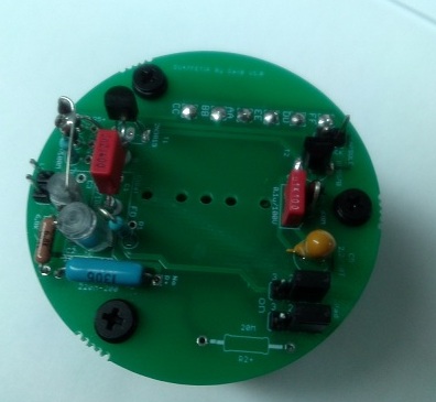
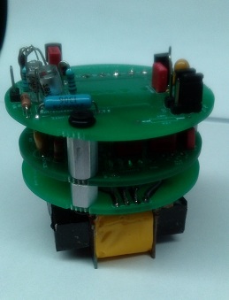
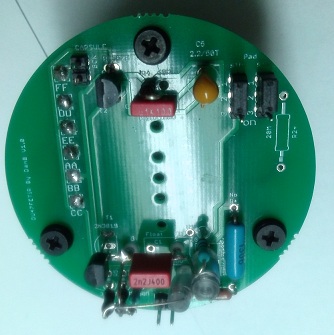
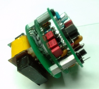
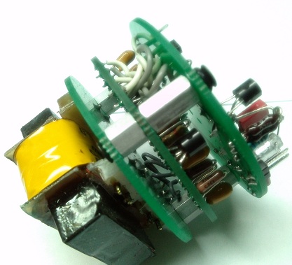
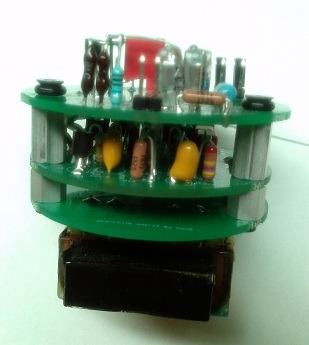
Do You mean Something Like This  ;)   A version i have but never used it yet , I am preparing this one for a customer,  it has been made for the U47 3 railing body like the AMI and/or IOaudio, So it is round , as you notice I also added a O-ring supension set that suppose to work in my favor.  it is indeed a lot of fun ,

I might have only one Left but not sure, Let me know if interested,

D-47FET    3 Railing system (AMI-IOaudio) microphone body type.
  i am working with Oliver to have the tube Cut , i am expecting a prototype soon, so will see,

58d1402a067ed.jpg


58d1402a06819.jpg


58d1402a06829.jpg


58d1402a0683a.jpg


58d1402a0684b.jpg


CAM00163.jpg


58d028199401c.jpg


micaddict... sorry, didn't mean to rewrite the Magna Carta, I started describing what I wanted to do and tried to justify my whim... I'll try to follow your advice in the future.

poctop: yes that is the idea, although I am inferring that assembly was created for a u47 body. My AT has an internal diameter of 44.5mm and a height of 38mm. If those dims are compatible I'd be very interested as it would save me a ton of work. If the diameter is a fit, but the height out of spec, would using a transfo like a T13 work?
 
I'm fortunate enough to have one of these in the works (thanks Dany! ;)).  How easy would it be to  implement pattern switching?

Apologies if this is something that has been gone over.

 
Jim50hertz said:
I'm fortunate enough to have one of these in the works (thanks Dany! ;)).  How easy would it be to  implement pattern switching?

Apologies if this is something that has been gone over.

the original design of the U47FET has been made to render this mic very special since it has only one pattern available wich is in this case Supercardiod as opposed to cardiod resulting in a very nice flatting transient response and very tight pattern something like in the middle of figure 8 and cardiod to my ears, implementing a patttern switching would be doable-DIYable by adding a cross polarisation scheme and feedback-filtering as simple as the M49 pattern scheme for example and of course a switching for  both side,  but i would alter this solely purpose of this mic,  the M49 Style mic would be something to reference to.
as the  ''lengend''  ;)  says the U47Fet original capsule were the K49 style that did not meet the matching on both side so Neumann would take those capsule and put them in the U47Fet making it this very special animal in that time , so very different minding as putting a one sided gold depostion diaphrgame as in the TLM49 

Best,  ;)
DAn
 
Guys,

if i wish to remove the 10db pad and the low cut filter, which parts do i not stuff?


many thanks in advance

Michael
 
Back
Top