Neumann U67 Clone : D-U67 Tube Microphone Build Thread.

GroupDIY Audio Forum

Help Support GroupDIY Audio Forum:

This site may earn a commission from merchant affiliate links, including eBay, Amazon, and others.
Hello and thanks a lot for this great thread!
I tried to use DU67 on Drum kit, Bass, guitars...
Here is a picture of my last recording. My two DU67 works really well!!!
I'm a really happy guy!  ::)
DU67 vs SM57 vs E906 vs C414 vs Schoeps CMC5!!!  ;D
And the winner is... DU67 and Schoeps CMC5 on distorted rock guitars...

I'll try to post pictures of mics, PSUs and samples as soon as possible.

Good luck to everybody,
Best

Olivier
 

Attachments

  • DU67 Blind Test.jpg
    DU67 Blind Test.jpg
    576.1 KB
Joekkel said:
hi there,

so my measurements with the tube and capsule connected are:

H-: -6.3V
B+: 210V
[a]: 3.22V

what should the [a]-pad measure? all measurements are to ground.

thanks and many regards,

The <a> refers to the anode voltage or plate voltage it should be like 75V ,  so it seems you have no plate current , either a bad tube or something arround the plate resistor Node R14 -C9 ,  check cold solder on the tube socket as a start and arround the tube, 
Best,
Dan,

joachim
 
Hi,

i'm mounting the capsule right now but i can't figure out how to wire it.  ???
all the pictures i see are not clear enough to understand where the wires go.
+ i see on the tskguy capsule a mark on one side of each capsule is that the "front" ?

on page 13 there's some info but still lots questions.

1- Front diaphragm center lead goes to right side turret (if holding the mic straight up and the tube facing you)
on POCTOP pictures means : right turret -> GREY CABLE -> front diaphragm
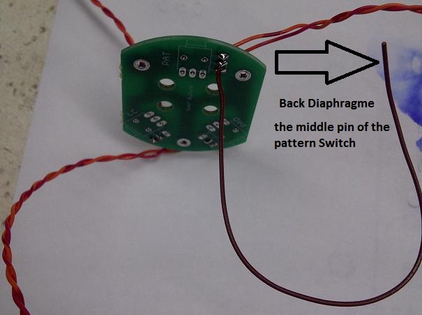
2- Rear diaphragm center lead goes to pattern switch pin 2 (actually soldered to the switch)
on POCTOP pictures means : PAT switch pin2 -> BROWN CABLE -> rear diaphragm
3- backplate lead goes to left turret (mic orientation same as above)
this i don't understand. capsule has 2 wires. do i have to add extra wire with screw on the metal part around the capsule in one of those little holes coveered by transparent plastic there ? any hole should be ok ?
on POCTOP pictures would mean : left turret -> ORANGE CABLE -> capsule "backplate"

any hi rez picture on this part or some diagram i could read ?
thx
 
1-1.jpg

58d0281993d57.jpg

Hope this helps,

Refer to M269b build thread for pattern switch and low cut and pad,
Dan,

Yes you need to have the backplate ( metal part of the Capsule connected via a screw eylet) and then wired to middle pin of pattern switch , what i usually do is to have a pre existing lead on the switch board that goes up to the basket ,
 
i have a question about plate voltage tolerance. I had a Tele tube that was a bit noisy, so i ordered a couple of Aperex Bugle boys tested for low noise.
The sound floor is definitely better. I am seeing about 85v on the plate, around 1.7v between r10 and r11.
My heater is about 6.1. Right now my B+ is a little high at 213v. I can trim it down, but its still going to be around 80-82 i imagine. Would this be considered in spec? My cathode seems cool, so i am assuming that is much more important
Thanks
Ian
 
dam  :D .. i was soldering wires close to that large Film Capacitor and i burn it a little :p
do you think it's ok or i have to change it ?
https://lh5.googleusercontent.com/-cG1e2gaw298/UZacvcHxY4I/AAAAAAAABBo/VpjXJmaaS88/s800/IMG_2112.JPG
https://lh4.googleusercontent.com/-wqBQjRvz9Bw/UZactkAzw4I/AAAAAAAABBc/RzOQMXXEJIo/s800/IMG_2111.JPG
https://lh4.googleusercontent.com/-AvkpCCVCTOY/UZacsr0v2UI/AAAAAAAABBY/mUB79cDKGvY/s800/IMG_2110.JPG
https://lh3.googleusercontent.com/-5ae6Njz0hdI/UZacrhiqKjI/AAAAAAAABBQ/4ecUNYcyjwo/s800/IMG_2109.JPG
 
no ideas on the plate voltage, as to whether it is too high? I know that it is kept lower for more clean headroom, but would it being in the low 80's be too high to be in spec?
My cathode resistor seems to be right where it should, so the plate current seems in the ballpark
 
Hello Everybody,
I'd like to share some pictures of my build...  ;D

best,
Olivier
 

Attachments

  • DU67_front.jpg
    DU67_front.jpg
    838.5 KB
very nice build nolivdacom i'm surprised how you passed the wires from tran pcb to main pcb ! i can not see them  :eek:


Thanks!  ::)

how you passed the wires from tran pcb to main pcb

I passed wires between PCB and Transfo. There is enough space so you don't have to passed it the same way as other wires. It works well and I've got more space around the tube. It's the cleanest way I found to do it, maybe not the best... Hope it's understandable  :D

best,
Olivier
 
good news!! c9 was busted so i replaced it. now the mic works like a charm! i was irritated by the crackling and popping at first, but this disappeard after some burning in of the tube. thanks poctop for helping and making this possible!!

i have the k67 from chunger installed and like it a lot, so... is the capsule from tskguy really so much better?

many regards to all of you! enjoy your new mic as i do ;)
 
a (noob again) question about flux.
in my other projects i didn't clean flux because there's not much and i don't use extra flux.
now this is my "smalest" kit and i wonder if it is super important to clean the board cause i don't exactly know how to do this ?

as i understood from main topic : 0.1A fuse for europe 210v is fine ?
 

Latest posts

Back
Top