Spencerleehorton
Well-known member
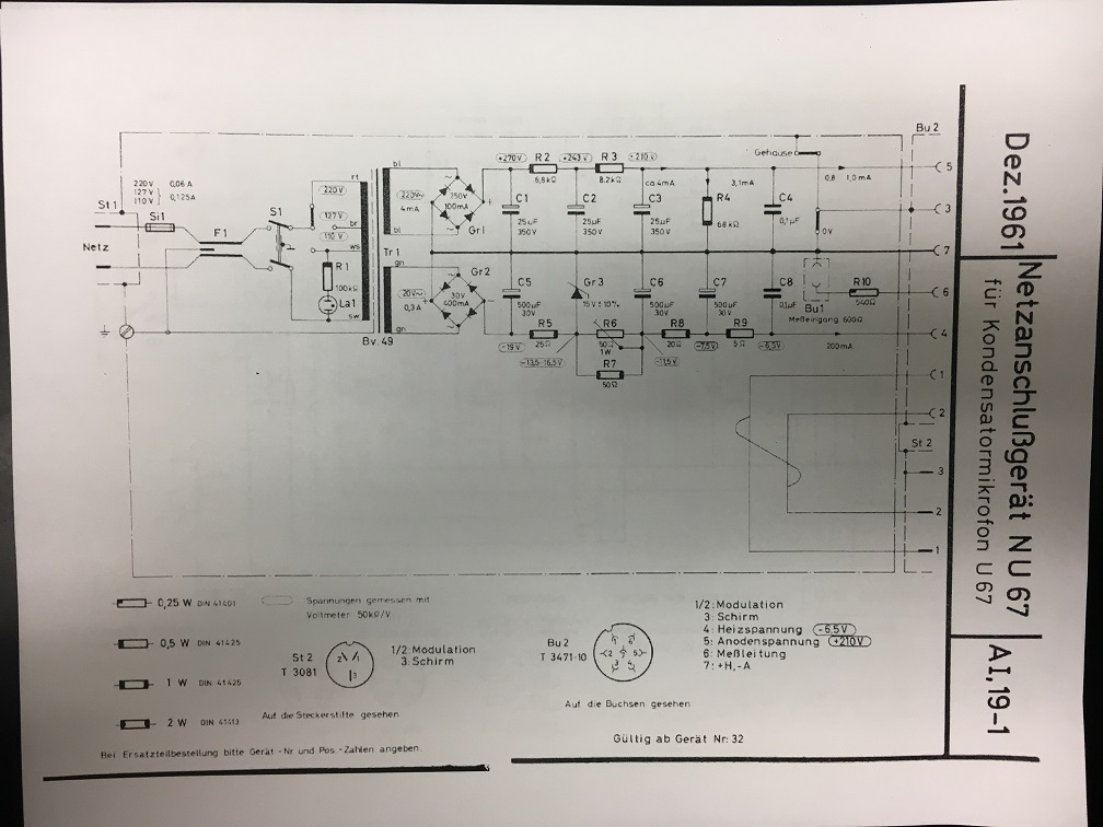
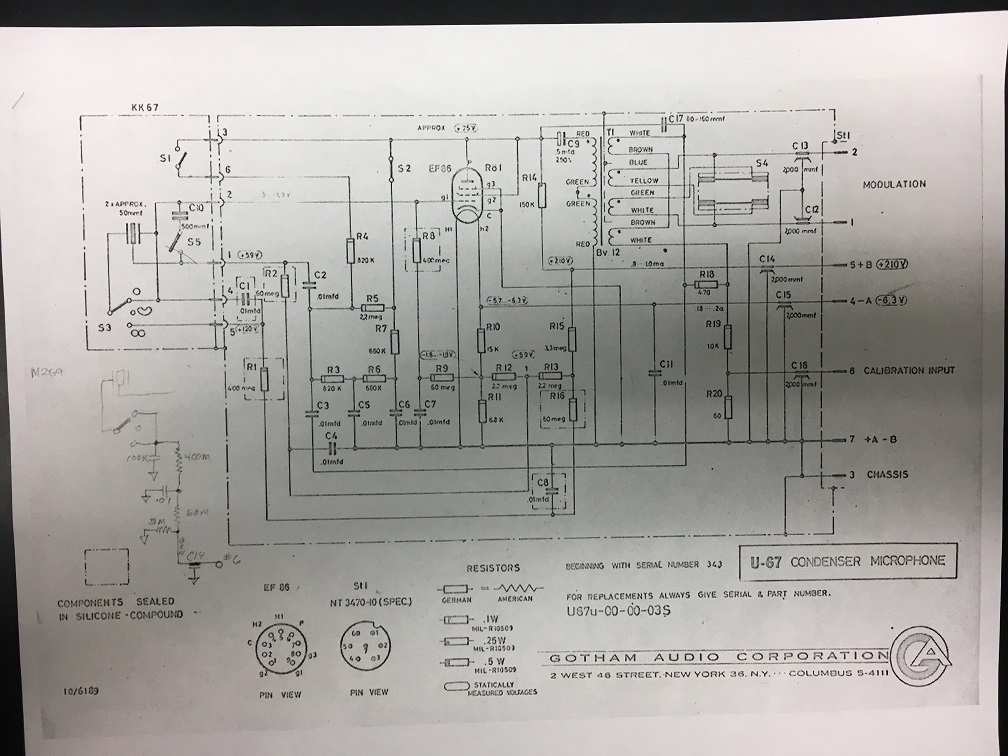
Looking at Danys schematic i see now:
Ive rewired and to my mind it disconnects 0v from chassis whilst still keep chassis to mic?
Spencerleehorton said:well i'm pretty certain i have it now as per the schematic.
One other question was the polarity switch, when i touch the switch i get a hum? any ideas? its not connected to anything gnd wise as the actual bit you touch isnt connected to any part of the rest of the metal of the switch?
It may not do it now i have rewired it!!! i will check.
Dany is saying it need a connection to chassis from 0v and others are saying there doesnt need a connection?
dmp said:"0v"=audio ground=pin 7 of mic cable
"shield"="chassis ground" = pin 3 of mic cable
For safety the mic3 connector coming into the PSU should be hardwired to the PSU chassis and the "mic-3" pad - and the IEC gnd should also go to the chassis. I think everyone agrees on this.
0v and shield are connected on the mic pcb (look at the schematic). The SHLF connects them optionally on the PSU pcb (a second connection). I did build a neve preamp that had a slightly lower noise floor once with multiple connections between audio and chassis ground. I am throwing in my two cents, but Poctop is the designer of this project.
Ultimately, as long as the mic is safe, you can try different things out for the ground scheme. As I've posted my U67 works great and has a low noise floor at my recording space but had a bad ground hum at another location once.


mohausler said:Just a quick note to say good this project is. I am stunned. Thank you poctob!
Fab Transformer & Heiserman capsule (plus a Valvo EF86) turned out to be a great combo. I have used many original 67s and this clone sounds stunning. Thank you!