wave
Well-known member
Thanks Dany!
I plan on working on the build manual this weekend. I have around 220 pics of my build.
Dave
I plan on working on the build manual this weekend. I have around 220 pics of my build.
Dave
Delta Sigma said:Waiting on my capsule, body and a few resistors that were back-ordered from Mouser.
In the meantime I thought I'd post a photo of my mostly completed power supply. I made quite a few mistakes on this one since I'm trying to get renos done and when I should be sleeping, I find myself soldering.
I didn't think when I positioned the low voltage transformer and ended up having to turn the IEC housing upside down (no big deal). I then decided just to mount the toroidal transformer to the case (just to get it done), only to find an unused rack ear to mount it to, leaving me with a hole on the side of the case. Lastly, I only realized after I took a photo of this thing, that I put the lamp on the power switch side instead of the mic connector side. If I'm ambitious when I calibrate this thing I move it over.
dmp said:Built up the mic this weekend. Really a fun project!
I was wondering if a chassis ground connection is required? Should the chassis tab on the xlr be connected to pin 7 or 3? Using a multimeter, 7 and 3 seem to connect on the pcb.
And second question: what size screws are needed for connecting the pcb to the mic body with the cathedral pipes body? I found two that fit to get it together, but I want to order some.
Finally, the mic tube is a tight fit going on with the pcb in (I'm using max's bv12). The body is hitting the bv12. Anyone else have this problem?

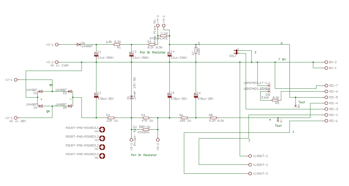
pin 7 is 0V and pin 3 the cable and mic body shield they join to the psu pcb only if SHLF jumper is installed on the pcb if not then you need to connect the shield pin 3 to the mic pcb this permits having 2 diefferent grounding scheme,
Check the schematic here to better understand
dmp said:pin 7 is 0V and pin 3 the cable and mic body shield they join to the psu pcb only if SHLF jumper is installed on the pcb if not then you need to connect the shield pin 3 to the mic pcb this permits having 2 diefferent grounding scheme,
Check the schematic here to better understand
OK - that makes sense. So I can choose to connect 7&3 on the mic pcb by wiring xlr p3 to the pcb (7 and 3 are always connected on the mic pcb) OR not wire p3 to the mic pcb, and install the jumper to connect 7&3 at the psu pcb. Two options for connecting audio ground to chassis ground. The original u67 schematic shows them connecting in the mic, and that p3 is connected to the casing (gehause). How does pin 3 connect to the mic body in this build? The xlr tab I was talking about was the tab on the 7p xlr in the mic. That tab connects to the body.
I did think that the screws on the sides were rubbing, but when I took the mic back apart the copper foil on the transformer had been ripped at the back corners. I'll check it's installation and see if it can go down further.
How does pin 3 connect to the mic body in this build? The xlr tab I was talking about was the tab on the 7p xlr in the mic. That tab connects to the body.
The xlr tab I was talking about was the tab on the 7p xlr in the mic
Enter your email address to join: