Neumann U67 Clone : D-U67 Tube Microphone Build Thread.

GroupDIY Audio Forum

Help Support GroupDIY Audio Forum:

This site may earn a commission from merchant affiliate links, including eBay, Amazon, and others.
Reallyjake said:
I’m having the same issue. It helped to lower both voltages.  I also checked inside the mic to make sure nothing was shorting to the mic frame. I’m trying a new tube after Memorial Day and will report back.

Were your voltages high? My working mic is running a little higher (but both within good range). I also tried with the casing removed to test that issue - obviously it hummed a lot but I could still clearly tell that the same issues were occurring with the polarity patterns. I might swap tubes see if that helps but I've swapped tubes and capsule previously with no luck...

I feel like if its passing signal its got to be close! Almost certainly some dumb error I've made but I've been over it with a fine tooth comb several times.
 
mickdundee63 said:
Hi guys, trying to trouble shoot my build.

I get a relatively normal sound in cardiod, and the rear diaphragm cancels out as it should. Omni also seems ok. In figure 8 the rear side sounds normal but the front side is very thin, like there's an aggressive high pass filter on it. It also seems to have a low output generally in cardiod and omni (compared to my first successful build) and I'm getting some interference noises from the computer which I've heard on other mics which have had grounding problems (and were fixed by addressing the grounding issue).

When I put it into figure 8, sometimes it makes some loud thumping noises for a few seconds as well.

Heater and B+ are in range, I've had a good look around and cleaned things up, but no luck, wondering the best place to start troubleshooting. I have my previous build as well which is helpful for comparison, but haven't turned up anything so far.

As a follow up - are loud pops when changing patterns wrong generally? My working mic functions perfectly but does pop pretty nastily when I'm changing the pattern. I built both mics with the same BOM, I'm thinking maybe I should try replacing the switches in both??
 
Thankyou Jacob, so my mic 1 is working correctly, that's reassuring.

I pulled the pattern switch from the circuit on my mic 2, no change. I pulled the LC and the HPF and reflowed what looked like might be a cold solder on C2 and now the background interference noise has gone.

I'll update when I isolate what the problem was in case Jake or anyone else is experiencing similar issues.  Still seems to have a low gain but the noisefloor is pretty good now and I'm using a cheap capsule for troubleshooting so once I've sorted the switches I'll stick the k67 back in there and see how it compares to my mic 1.
 
Eh I spoke too soon. Tested this quickly late at night on a low gain, but the background static is definitely still there. Removed the whole switch assembly to eliminate that factor. Sounds nice now, more full than before, how I would expect it to sound but just this static issue.
 
Double-check your transformer wiring. There is a lot of information that gets corrected later on in the forum.
Also, double check your tube pcb wiring. I found some of the resistors and caps aren’t exactly where it the silk appears to say they should be. So I ended up having to fix two. Also, make sure you clean those pcbs with alcohol but not get those poly styrenes wet with the alcohol.
 
FarisElek said:
Double-check your transformer wiring. There is a lot of information that gets corrected later on in the forum.
Also, double check your tube pcb wiring. I found some of the resistors and caps aren’t exactly where it the silk appears to say they should be. So I ended up having to fix two. Also, make sure you clean those pcbs with alcohol but not get those poly styrenes wet with the alcohol.

This was very helpful. I noticed that I'm still getting the grounding noise with the PSU switched off so I could poke around a bit more safely, If i ground one of the transformer pins its significantly reducing the hum/static, but the mic still passes signal. So I think it might be in the transformer section. I think the tube pcb is ok, I've cleaned it up and compared it to my working mic. Will triple check the transformer wiring and consult the schematic so I can see what I'm actually poking at and what the issue might be.
 
Hey guys hope this message finds you well. I recently finished my D U67 build and wanna say thanks to Danny and every one else for making this project available. I love its sound. I mainly built it to use for drums and I am wondering since right now the sound picks up alot of cymbals could i maybe have it be more balanced or smoother on sibilance. I will have to note that the capsule i believe is a u87 from an unknown manufacturer but was sold to my friend as a replacement upgrade for an MXL(probably not the best). I used the cinemag updated version transformer with full frequency response.

Im wondering should i try a better capsule like beesknees or other. Or maybe a different transformer. Danny said i could try C17 of the feedback circuit.

Any opinions or knowledge would be appreciated. I love that this mic build thread group exists. Thanks in advance.
Tony Santos
 
ANALOGER said:
Hey guys hope this message finds you well. I recently finished my D U67 build and wanna say thanks to Danny and every one else for making this project available. I love its sound. I mainly built it to use for drums and I am wondering since right now the sound picks up alot of cymbals could i maybe have it be more balanced or smoother on sibilance. I will have to note that the capsule i believe is a u87 from an unknown manufacturer but was sold to my friend as a replacement upgrade for an MXL(probably not the best). I used the cinemag updated version transformer with full frequency response.

Im wondering should i try a better capsule like beesknees or other. Or maybe a different transformer. Danny said i could try C17 of the feedback circuit.

Any opinions or knowledge would be appreciated. I love that this mic build thread group exists. Thanks in advance.

Tony Santos
A better capsule will definitely help and it will have the biggest impact than any other component. BeesNeez makes great capsules and they have this “mellow” kinda aged sound...a touch darker and creamier. I have their 87 style capsule in a d87 I build and it sounds extremely close to our vintage 70s u87...you can do punch ins.
The c17 plays also a big role depending on transformer. On my 67’s I have 150pf in one and 180 on the other. People have gone higher than that.
Then it’s the tube. To mellow it out try a Mullard ef86 or on the cheap a great mellow tube with great midrange is the NEC ef86.
I would try capsule and c17 cap before the tube though.
 
So I solved my ground issue - saw a post in this thread about connecting ground/shield/cable housing at both ends - worked for me! I re-installed my switch assembly and same issues: cardiod is ok but low gain and not very full compared to my working mic. Figure 8 is full but dark at the rear and thin/tinny at the front capsule. Have been over every square inch many times hunting for a cold solder or error. All component values are correct on a visual inspection. I'm getting around 50v on the backplate - which is consistent across the working and non working mic.

At the junction of r14 and c9 I get 80v on my working mic but around 95v on the non-working one. R14's value is correct, I tested it with the multimeter. On my (very limited) understanding of the schematic this is supplying plate voltage so I wouldn't think it would affect patterns.

Is there anyway to check the polarisation voltage for figure 8? I'm not sure if the impedance issues mean I can't use my multimeter to check this?

Otherwise I'm going to start pulling and replacing components. If my backplate voltage seems correct I'm thinking R2/C8 are probably ok so will try C1/R1/C8 first.

Any other ideas?
 
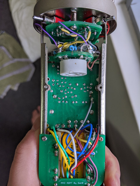
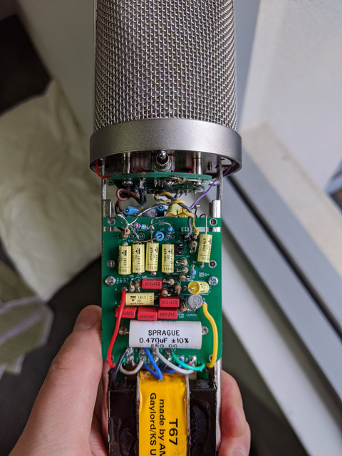
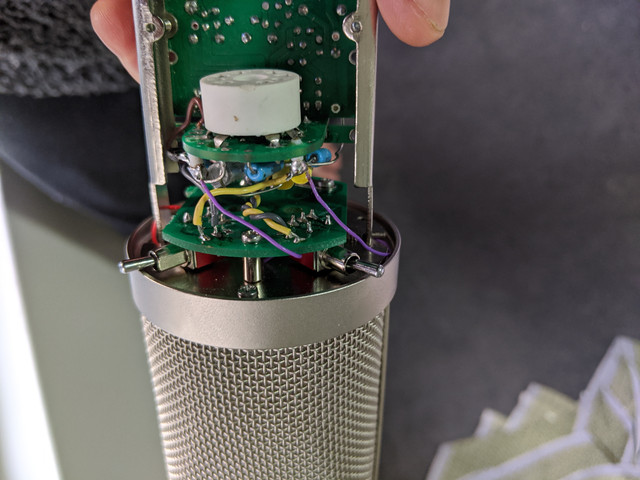
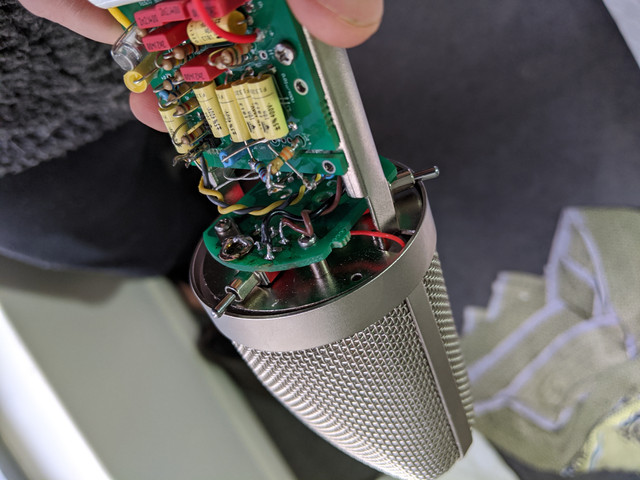
Take a picture of your build. Try to get a really clear and bright image of the front and back and as much as you can of the switch/tube wiring. You’ll be surprised at how obvious the problem can be someone’s and anyone who has worked on one of these before can probably point out a mistake as it’s a tedious build that’s hard to forget.
 
Faris Elek thankyou for the suggestion.

Happy to post more photos of any section if there's not enough information or something doesn't look quite right.

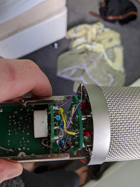
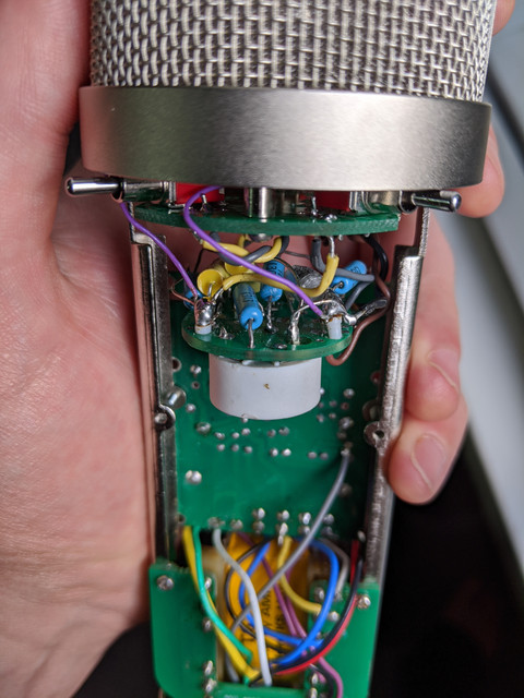
My build looks a bit untidy - that's because I've been pulling it apart trying to fix it. The pattern switch in particular looks ugly, I used that eyelet to ground the foot of the switch as it didn't have continuity to ground. But the switch checks out electrically on a continuity test and my problem is identical now to when it was tidily wired and meticulously cleaned with isopropyl alcohol (which I cannot get now - thanks COVID).

Some of the floating component wires look they are touching based on the perspective of the camera - but they're not.
 
mickdundee63 said:
Some more detail on the switches:


I am a newbie myself but with this kind of soldering you are lucky your first one is working haha...all joking aside I think the first thing you should do is go over your joints with a magnifying glass and make sure you joints practice proper “social distancing”. Then check for cold joints
 

Latest posts

Back
Top