@wink0195
Hi Andrew,
wink0195 said:
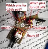
Ok, I can for sure cut all the leads and solder directly to the switch pins, but which pins on the switches do I attach the 2 - 3 pin ribbon cables to so that they match up with the indicated patterns? and how do they coordinate with the pcb?
I labeled the pins "1,2, and 3" so you could easily explain via message where i should solder the ribbon leads, however, "PAD" and "LC" on the PCB aren't labled "in" and "out" either so plz just refer to them as "Pad PCB left" and "Pad PCB right" in coordination to looking at the silkscreen labels side of the pcb. do you follow me?
Also did I cut all the appropriate leads? I don't wanna short out my back plate :'(
(Click on thumbnails to enlarge and view properly)
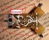
O.K. so far,but you must cut the trace ground to the left (pattern?) switch too.Can be done with a sharp knife,it´s easy.
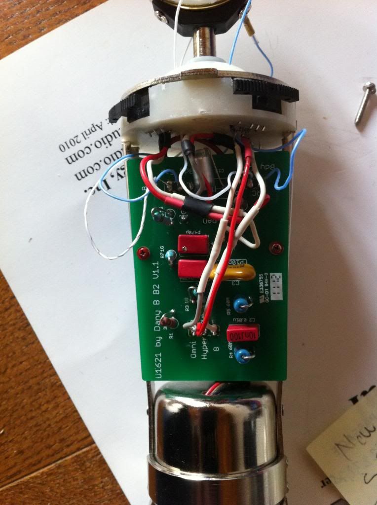
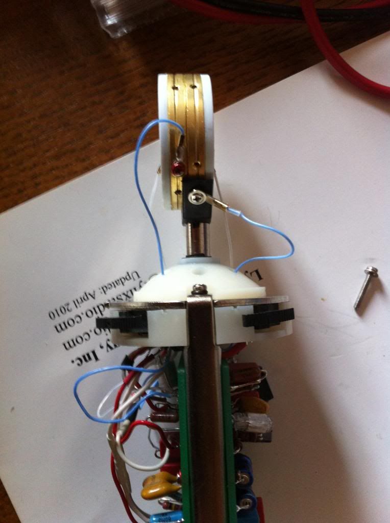
One thing that is imperative here:Since I don´t know how this board is mounted inside your mic it is best to run a wire from the board ground to a good point on the pcb or the mounting rails.The switch board ground connections are connected to their metall plates surrounding the switches.These are meant as shields.If not done properly the switch knobs themselves act as an "antenna" and can pick up rf-noise.When touched you would get an ugly hum too.Quite a few guys here did this wrong from what I remember.
The big ground pad on the left (on the switch board) will serve you well.
wink0195 said:
As said I don´t know which side show upwards or downwards nor do I know how your housing s labelled.
But don´t worry,it´s an easy one!
All the what you named "pin 2" connections are used.For the HPF and the pad it doesn´t matter to which of the dual connection on the main pcb they go to.But the pin 2 of the pattern switch must go to the middle connection of the triple pad on the main pcb!
Next step is to figure out which pins (1 or 3) goes where,it´s easy again:
When looking at the labels and where the knob tips show to-it´s always the oposite outer pin that refers to it!
Think toggle switches acting like a "seesaw"(hope that is the correct english word?).
An example:The switch knob tip shows to the left means the middle pin and the outer right pin are connected (ohm that out if you want).Same on the other side,tip shows to the right means middle pin connects to the outer left pin.That´s it!
The only difference is the pattern switch that has a middle position.In this case the pin 2 simply connects to nowhere.
So for the HPF and the pad one side of the switch is unconnected,the pattern switch uses all 3 connections.
Have found a nice additional explaination on how switches work,see the second drawing:
http://www.musicfromouterspace.com/analogsynth_new/ELECTRONICS/pdf/switches_demystified_assembly.pdf
Hope it´s all clear now,you´re getting pretty close to it!
Best,
Udo


![Soldering Iron Kit, 120W LED Digital Advanced Solder Iron Soldering Gun kit, 110V Welding Tools, Smart Temperature Control [356℉-932℉], Extra 5pcs Tips, Auto Sleep, Temp Calibration, Orange](https://m.media-amazon.com/images/I/51sFKu9SdeL._SL500_.jpg)


