Neumann Vintage U87 Clone : Build Thread.

GroupDIY Audio Forum

Help Support GroupDIY Audio Forum:

This site may earn a commission from merchant affiliate links, including eBay, Amazon, and others.
HellfireStudios said:
Well, I finally got my studio built, and have started tracking the local talent. I was tracking a female vocalist with the U-87 clone, and a problem arose. I'm getting a high-pitched whine off of the mic (seems to be around 12-13kHz). It also seems to swell in and out of the track (maybe a faulty capacitor?). Unfortunately, I was unable to discern this cricket-like and intermittent noise during tracking, and may be doing a free session or two to make up for the problem (EQ and noise reduction have been unsatisfactory tone-wise).

Other than an ungrounded polar pattern switch acting as an antenna, what else should I check out? I appreciate any help that can keep this from happening to someone else.

BTW, the mic sounds amazing otherwise. I'm using the Peluso K-87 capsule and BV8P-S transformer wired for 11:1. Styrenes and tantalums except for a couple of silver micas replacing the styrenes that were unavailable at the time. Fairchild 2N3849 FET biased with a oscilliscope. Full 48v phantom power from the included standalone P/S that comes with the Carvin CM-87S. I also added the polar pattern switch because the mic only had low cut and pad switches stock. Which is why I hope it is just the switch case leaking RFI into the circuit, but the sound swelling in and out sounds like a capacitor issue to me... Let me know, if I need to post an audio example. Thanks again.

-James-

I would probably un-functionnalize the mic First ,

if you can reproduce the problem with the shell open  , then monitor the Drain Voltage.

the screeching noise and swell in-out , is probably caused that something that put the FeT out of a Job and it swings big time,

you could also inject sine tone in it , without the capsule to and confirm the hypothesis.

sounds like a capsule problem to me but can't be sure. , always then handy to have a testing kapsule even if it is a 67 then you can try the mic anywhay.

Always good to reverify the wire placement and also the intergrity of it when closing the mic body,


Hope this helps,
Best,
DAn,


Hello James,

are you sure it is just the microphone?
Anyway,switches housings must be grounded,they can do ugly things if not.Although one might think it could be a cap because there's a thing about time going on it is not a must- be.
Why?Rf fields are not always static,they can move,pulse or whatsoever.
Easy to do.Should be done anyway!

Other things one can do as a search to sort out things are:
Have you tried to replace the mic to another one (condenser) in the exact same signal chain?
Can you hook up the mic to a different recorder,micpre or console directly and monitor it?

Just some thoughts,a patchbay,the gear itself and other things in the whole signal chain interact,maybe it is an issue about different groundlevels or grounding schemes..........

I'd say do the ground on the switch as a first step,then try again.

Good luck,

Udo.

Edit:Typo.
 
+1 on all said and you can remove the switch wiring and just use the PCB jumper positions to test/confirm?

Also is it in all patterns, w/w-out pad, hpf?

Also looks like that is a different fet part# which as Dan points out could be driven to oscillation due to it's specific operating points / setup.

Cheers,
jb
 
Must have read the original post too fast,maybe that's the culprit,maybe it works,who knows.....
But anyway,it's sorting and grounding time,right ;D

Udo.
 
0dbfs said:
+1 on all said and you can remove the switch wiring and just use the PCB jumper positions to test/confirm?

Also is it in all patterns, w/w-out pad, hpf?

Also looks like that is a different fet part# which as Dan points out could be driven to oscillation due to it's specific operating points / setup.

Cheers,
jb

My apologies. I used the right FET, but gave the wrong number. I used the 2N3819 that was on the BOM.
Strangely enough, during my four hour testing today, I was unable to get a reproduction of the "cricket chirp." Although, the signal chain is different in my "lab." I guess I need to get back to the studio and test the rest of the chain. What strikes me as really odd is the fact that I recorded drum overheads through the same chain with a different mic an hour after the female singer left, and had no problems. Do you think the 48V P/S could be the culprit?

Step one: Ground that switch.

Step two: Retest the chain.

Step three: Call an exorcist because these studio gremlins are stressing me out...

-James-
 
HellfireStudios said:
Do you think the 48V P/S could be the culprit?
Sure,especially when it is an smps type.Remember you have a fully (virtual?) grounded connection to your pre from it.
Not so good for audio when done the cheap way,that´s why I prefer linear types.
Bad phantom power can seriously hurt your signal!

Best,

Udo.
 
Anyone who has installed the RK-87 Cap can you please post a pic of where you attached the blue wire to that came with the capsule? Specifically, where to I screw the tab to? the directions on the Microphoneparts.com website are confusing on where to attach this small wire to. I have been following chungers post but he uses the Peluso and there is an extra wire on the peluso capsule that mine doesn't have.

I am trying to wire this mic up using the cardiod?

Also how do I test this mic without an oscilloscope? Seems everyone here has used an oscilloscope.

Sorry if these have been answered but after an 1 1/2 hours of just looking for a picture or specific answers, I decided just to ask...I'm frustrated and a little confused  ???


Thanks
G
 
Toure14 said:
Anyone who has installed the RK-87 Cap can you please post a pic of where you attached the blue wire to that came with the capsule? Specifically, where to I screw the tab to? the directions on the Microphoneparts.com website are confusing on where to attach this small wire to. I have been following chungers post but he uses the Peluso and there is an extra wire on the peluso capsule that mine doesn't have.

I am trying to wire this mic up using the cardiod?

Also how do I test this mic without an oscilloscope? Seems everyone here has used an oscilloscope.

Sorry if these have been answered but after an 1 1/2 hours of just looking for a picture or specific answers, I decided just to ask...I'm frustrated and a little confused  ???


Thanks
G

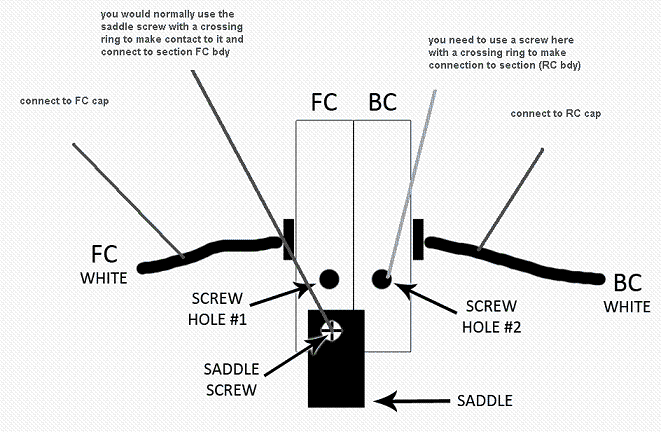
To establish functionnality of the capsule you need 4 wires in total ,
2 are the backplate
2 are the diaphragme ,
Here a summary of what you need to do
58d0281993e90.gif


you basically need an eylet mounted on the capsule support to make contact with one of the backplate and the other backplate has its own wire
and then you need the 2 wire from the diaphragme,

the ocscilloscope is used to bias the FET,  if you dont have one you can set the drain voltage to approx 11.5V and you will be in the ballpark ,

there is a link that show how to do it in the first page of the thread ,

to install the mic in cardiod only , you need to attach the front backplate and the front diaphragme in the respective pad ,
such section FC    (FBK = front backplate and FD the front diaphragme ) then with no jumper installed on the pattern jumper you will be in cardiod mode ,

alot of info are presented on the first page of this thread also ,

Hope this helps,
Best,
Dan,
 
I'm very interested in building a U87 clone and have followed this thread for a while. 

To those well experienced in building these 'homebrew' U87s - is there a universally accepted 'best donor mic' I should be looking at to get this project underway?  I see there are many options listed on page one of the thread -  - just curious if any particular mic is considered the best starting point?
 
Hi,

if I were you I'd probably choose a body that is proven to fit Dan's pcb,remember there are two versions.
Unfortunately Chunger's SYT-5 still seems to be sold out.
Could be done in most mentioned bodies,just be aware that if you go for full switches you might have to change the labels (I had to do so on Be*****er B2Pros as an example).

Best regards,

Udo.
 
Just a heads up...

I just completed my first U87 build in the GXL body. I was pretty excited to have it done, but then I was almost immediately reminded I had all the goofy logo stuff on the body.

As it turns out, a little bit of Nail Polish Remover from your local beauty mart will take that stuff right off. Just dab a napkin or toothbrush into some NPR (Acetone) and scrub it away. So far I've tested this on the Global Audio GXL2200 and NADY SCM900. The black powder coat stays on and looks great! Say hello to unbranded microphone bodies!  8)
 
Hey, guys. I've put my DIY U-87 through three different sessions since it gave me the weird high-pitched whine underneath the audio, and it hasn't happened again. I took it back to the live room once without the switch grounded to test it and all of the recent sessions with the switch properly grounded. I could not elicit an extraneous noise at all. I'm happy that whatever the situation was has resolved itself, but still on edge about a relapse. The fact that the audio may need to be scrapped isn't something I look forward to telling the artist either...

-James-
 
Che_Guitarra said:
I'm very interested in building a U87 clone and have followed this thread for a while. 

To those well experienced in building these 'homebrew' U87s - is there a universally accepted 'best donor mic' I should be looking at to get this project underway?  I see there are many options listed on page one of the thread -  - just curious if any particular mic is considered the best starting point?

I just used the Nady SCM900 and GXL2200. Both were very easy to take apart and modify. I would recommend either. The only tricky part was the transformer mounting which chunger has a great zip tie solution for. The MXL 2001 is also almost identical but includes an enclosure for transformer placement. I'd recommend any of those 3.
 
Hey Guys,
I finished the baby but it's so low sound that I am hearing... I calibrated it so I got 11.4V and 48V also well as like below;

Phantom:   47.86V
Top of R18: 47.8
Bot of R19: 47.8
Node R18/R19: 46.68V
Zener : 23.83V
node R12/R14: 19.71
FET Drain :  0.42V     
FET Source: 0.32V

I didn't put yet 10K resistor...
any idea what's happen here?  :D

Thanks
 

Latest posts

Back
Top