Neumann Vintage U87 Clone : Build Thread.

GroupDIY Audio Forum

Help Support GroupDIY Audio Forum:

This site may earn a commission from merchant affiliate links, including eBay, Amazon, and others.
poctop said:
Nyquist said:
Nice work on the write up mate.

+1 Awesome , Very Nice of you to share that with the comnnunity,
Best,
DAn,

As long as we're calling the B2 a donor body, we might as well have some guidance on how to do it with ALL the B2s  :) Glad I could finally contribute something after years of lurking and not finishing much  ;D
 
jasonallenh said:
poctop said:
Nyquist said:
Nice work on the write up mate.

+1 Awesome , Very Nice of you to share that with the comnnunity,
Best,
DAn,

As long as we're calling the B2 a donor body, we might as well have some guidance on how to do it with ALL the B2s  :) Glad I could finally contribute something after years of lurking and not finishing much  ;D

you actually did a lot,
updated first page of this thread with the precious and really colligated information ,
by Jasonallenh
Thanks again for doing that,
Best,
Dan
 
Yeah, great indeed.Thanks!

A couple of questions if I may.

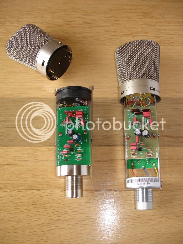
It says B2, but I see a B-2 Pro. Not to nitpick, but to avoid confusion as the B2 does not have the three patterns.

Also, I see "American" B-2 Pro. In what way is that different? Or does it just mean the older version with the detachable head?

Here's a picture I took of the old (left) and new (right) version:

DSC02496.jpg
 
Using the latest blue board 1.3... pattern switch pads are marked 1,2,3 and the pattern wires pad are 8, crd, omn. Which goes to which?
 
rob61 said:
Using the latest blue board 1.3... pattern switch pads are marked 1,2,3 and the pattern wires pad are 8, crd, omn. Which goes to which?

if the contact get shorted between crd-omn then it is omni,
if the contact get shorted between crd-8 then it is fig 8
if nothing is shorted then it is crd = cardiod,

best,
DAn,
 
I was looking for an Ociloscope for testin my build I the u87 and was wondering what you guys would recomend? I would like decent  one under $200, if that is possible.
 
hi mates, so i finally received all of my parts from mouser and just radios and i was going through the bom to verify i have everything when i noticed that the excel BOM says i need (4x) 22-28-4020 Headers & Wire Housings 2C HEADER Sn/Pb, wheres on the mouser BOM it only includes (2x)   

i was just wondering who has the error and if i only need 2 or 4...

would appreciate if any of you guys who've built one already could chime in.

oh, another thing are the 10x jfets included in the bom enough to find a 4% matched pair or do i potentially need to order more to get in that spec?
kudos.
 
These are the 2-pin headers. The build allows for different options, so it depends what you plan on building.
If you're using jumpers on the pcb (because your donor body doesn't have switches) for the pad and low cut then you need one for each of these (total of 2). You obviously also need the jumpers to stick on them. If you're short of parts then you could leave them out initially - the mic would default to no-pad and no-low-cut which is probably what you want.
I also used 2 more for making the connections to the pcb from the capsule - I think some builders may solder the wires from the capsule directly to the pcb, but it makes it easier to unsolder them if you use header pins. I'm not sure what Dany originally intended for this, but I'm sure either method works.

I know this is a very long thread, but it's worth reading before you begin. If you haven't built a mic before you need to pay close attention to cleaning the boards with isopropyl alcohol - any solder residue in the high impedance areas will impair the mic performance.

As to the matching - you may get lucky with 10 parts seeing as they're almost certainly from the same batch. I got 2 identical (to within 0.1mA) in a lot of 20.

Good luck with the build.
 
i have 7 isolation turret pins and my mic body supports all 3 switches, so those molex pins are just included for the mic bodys that don't support the switches?

 
errba said:
i have 7 isolation turret pins and my mic body supports all 3 switches, so those molex pins are just included for the mic bodys that don't support the switches?

Right - unless you want to use them as I did for the capsule wires, in which case fit them in the FC and RC holes. I think I'm in a minority with that method, but it's your build, so feel free to adapt/improvise as you wish - it's encouraged round here.

On the turret pins - you only need one for the regular boards, or 2 (I believe) if you're using the newer 'M' boards (the ones that accommodate the transformer on the board). If you're using the 'M' boards then see the build guide here - http://vintagemicrophonepcbkit.com/Neumann%20U87%20Build.htm
I don't know why you have 7 turret pins - the BOM on Mouser (v1.6) shows 2. The BOM used to allow for all the different options, so you may end up with a few surplus parts. If you have surplus parts, just view them as a downpayment on your next mic build  ;)

Best,

Ian

 
Hi,

I've built my du-87 late 2012, but I think I have a problem with it and I would really appreciate your input on this one.
So I have built several mic projects from the forum and they are all exellent but this particular U87 sounds really dull and nothing like the samples I have heard from you guys  and I haven't found a single source I would use it(paired with oter mics it almost sounds like "broken").  It's SYT-5 with hk-87 capsule(from 2012) and Ami T-13, other components are straight from Poctops mouser cart (styroflex caps).

I will attach a vocal sample recorded today using Api 512 pre to Ua apollo I will also link a file witch is Chungers sample using the exact configuration.

What do you think? Could it be broken transformer, capsule  or some component/build problem?

Thanks in advance!

My du-87
https://www.dropbox.com/s/uvqgk6mqsf1xjuv/U87.mp3.mp3?dl=0

Chungers sample
https://app.box.com/s/omsbvvdxm5w1bd3i4h1f
 
sedit1 said:
...
What do you think? Could it be broken transformer, capsule  or some component/build problem?
...

There was a problem with some of the Ami transformers' wiring being reversed - read back in the thread from around here - http://groupdiy.com/index.php?topic=48030.msg732325;topicseen#msg732325
Make sure you haven't got that problem.

I don't have great ears, but I don't hear any glaring problem with the mic - it sounds quite neutral, as it should.
Hopefully someone with better ears will be along soon.
 
Krumlee said:
sedit1 said:
...
What do you think? Could it be broken transformer, capsule  or some component/build problem?
...

There was a problem with some of the Ami transformers' wiring being reversed - read back in the thread from around here - http://groupdiy.com/index.php?topic=48030.msg732325;topicseen#msg732325
Make sure you haven't got that problem.

I don't have great ears, but I don't hear any glaring problem with the mic - it sounds quite neutral, as it should.
Hopefully someone with better ears will be along soon.

Thanks,

No the Ami is not reversed it's working like it should be..The most noticible problem is big low middle bump and the mic sounds dull, nothing llike U87 iv'e used or heard.
 
sedit1 said:
Krumlee said:
sedit1 said:
...
What do you think? Could it be broken transformer, capsule  or some component/build problem?
...

There was a problem with some of the Ami transformers' wiring being reversed - read back in the thread from around here - http://groupdiy.com/index.php?topic=48030.msg732325;topicseen#msg732325
Make sure you haven't got that problem.

I don't have great ears, but I don't hear any glaring problem with the mic - it sounds quite neutral, as it should.
Hopefully someone with better ears will be along soon.

Thanks,

No the Ami is not reversed it's working like it should be..The most noticible problem is big low middle bump and the mic sounds dull, nothing llike U87 iv'e used or heard.

I beleive somthing is not right as the mic sounds very harsh from your sample,
i would definitivley check on the capsule and try another one to rule that out ,
Best,
Dan,
 
poctop said:
sedit1 said:
Krumlee said:
sedit1 said:
...
What do you think? Could it be broken transformer, capsule  or some component/build problem?
...

There was a problem with some of the Ami transformers' wiring being reversed - read back in the thread from around here - http://groupdiy.com/index.php?topic=48030.msg732325;topicseen#msg732325
Make sure you haven't got that problem.

I don't have great ears, but I don't hear any glaring problem with the mic - it sounds quite neutral, as it should.
Hopefully someone with better ears will be along soon.

Thanks,

No the Ami is not reversed it's working like it should be..The most noticible problem is big low middle bump and the mic sounds dull, nothing llike U87 iv'e used or heard.

I beleive somthing is not right as the mic sounds very harsh from your sample,
i would definitivley check on the capsule and try another one to rule that out ,
Best,
Dan,

Thanks Dan for your comment!
That's what I've been thinking about too, so maybe it's the first thing to rule out because otherwise it's seems to work correctly.
 
Waiting on my pcbs and then I shall be ready for the build. Still wondering what is the setup you guys use for biasing. I see the o-scope and signal generator from Udo but I am wondering if I can just use a computer based scope or should I get an actual scope. I would like to try and keep the price under $200, what do you guys recomend I use?
 
Just  made u87 clone, but there was something not quite right

i did calibration with meter not with oscilloscope

got everything together and tested it with recording and everything above 4k was kinda missing.

So, i removed connections from capsule and transformer to make some measurements: 

i noticed that xlr out was 31,3 v  (that should be 48 v) (i did double check that phantom power is ok, 48v)

i tooked off the bias calibration to make sure its not the problem, xlr out was still 31,3v

input jack connection is ok (its 48v when i took wires out of bcp)

other measurements:

L1 32.1
L2 32.2

R18 31
R19 26

zener 24
R16 27
R17 24,5
R14 22.4
R13 26.0
R 12 12.0
R 9 0
R10 0
R8 23,8

i checked that connections between A-aa b-bb c-cc g-gg was ok

pad, lc and figure pattern connections are in use with body

Any suggestions where the problem might be?

BROBLEM SOLVED:

I  messed up with  with R10 and R17, somehow i had confused 56k and 560 r resistors, i feel like an ***** :)

Now its working perfectly!!!
 
Pcbs came in!! They look great!
Thanks to Danny.
But like an ***** I ordered the wrong ones. I have two b-2 pro bodies and I ordered the d-87m set thinking it would work. But looks like I will have to shave them down to get them to fit. I hope it works! I should have asked you guys wich ones to use.
Will keep you guys posted and will add pictures!!!!
 

Latest posts

Back
Top