Neumann Vintage U87 Clone : Build Thread.

GroupDIY Audio Forum

Help Support GroupDIY Audio Forum:

This site may earn a commission from merchant affiliate links, including eBay, Amazon, and others.
Hi

This seems like a really noob question but I just can't figure out how to wire the peluso p-k87i capsule to the pcb.

First, is the peluso a dual isolated backplate capsule? I found that the screws on either side is electrinically connected... So I guess not... :)

Also found this quote:
"When the U 87Ai was introduced, the K67 was employed again, as there was no advantage perceived with using the split backplate."

http://recordinghacks.com/microphones/Neumann/U-87-Ai#ixzz1pUMxOm2D

So what wires should go to cap and bdy on the pcb if both backplates are the same?

I'm planning to use only card and omni as I have bought the german version of the mic bodys suited for the project - the "Fame" microphone which seem very good for the job btw...

Hope someone can clear up my messy understanding of the circuit!

Cheers,
Kasper
 
in this case with the peluso capsule as the original K87  the 2 backplate front and back are isolated electrically this is guaranteed,

The Answer is the front backplate tab already on the capsule is for the front capsule so this is how you recognize the front , there actually on opposite side because of that  ;)
the (back) backplate will connect via a tab that you need to supply ( Peluso Wisher will be providede one) and attached to the mounting saddle connection so it will make contact will the back backplate only,

So the connection on the PCB are for FC = front capsule  (cap = capsule and bdy = backplate) and same for the back diaphragme  as the RC section on the PCB Cap= back capsule and bdy back backplate,

Hope this helps,
Dan,
 
please also note that since the backplate are isolated the tab from the front backplate is on the other side of the capsule hence creating your confusion , if you check continuity between the 2 backplate it will be an open connection
just play with the capsule with your ohm meter set to continuity check and you will find out pretty quick.

Dan,
 
Hi,
Please excuse my language if I make some english mistakes, I'm french, and I will try to do my best :)
First af all, congretulations for this great project!

I don't understand with what the soldering points "SW" and "RT" have to be link?
And do the "ground link" point need to be link with the mic body? and the "cground" point?

Thank you!
 
lefilsdejack said:
Hi,
Please excuse my language if I make some english mistakes, I'm french, and I will try to do my best :)
First af all, congretulations for this great project!

I don't understand with what the soldering points "SW" and "RT" have to be link?
And do the "ground link" point need to be link with the mic body? and the "cground" point?

Thank you!

what transformer do you have for the project that will help alot for the configuration ?,  the PCB B1 needs to make a solid contact on the mic body via the screws and pad from the pcb mounting hole, you can verify that after installation with a 0 ohm between the mic body and cgnd ,  the cgnd pad was used with the original transfomer wich has a core grounding to it if your transfomer does not have a core grounding you just simply omit this pad,  the Gndlink was designed in case where the head basket is not grounded to the mic body properly.

Note also that the Color code is the german color code as used in the original schematic see page 1 of the white market thread for the schemo or here Reference: https://cdn.groupbuilder.com/groupdiy/u/39511/58d0281993744 rev 16 schemo


it will help figuring any transfomer configuration.
Hope this helps,
 
I use the Cinemag transformer, so if I well understand what you said before, I don't have to connect those pads.
Thank you Dan!
 
poctop said:
please also note that since the backplate are isolated the tab from the front backplate is on the other side of the capsule hence creating your confusion , if you check continuity between the 2 backplate it will be an open connection
just play with the capsule with your ohm meter set to continuity check and you will find out pretty quick.

Dan,

Thanks Dan!

Now I have figured it out... As you said a little time with my meter and it all made sense.

To be sure - and for the fun of it - I completely disassembled the stock "Fame" capsule. :)

In 30 min I have learned so much about capsules :)

Cheers
 
LefilsJack and Kasper , Please keep us posted of your finding and sucess I hope :)

Dan,
 
wthrelfall said:
Matador

I dropped R17 so I now have 23.5 volts at the zener (i can't get it exactly to 24v as I don't have a large range of resistors).  doesn't the voltage at R12 depend on the R11 value?  I mean as soon as I adjust R11 to bias the fet then R12 just tracks this voltage from the fet drain.  so I don't understand how I can get R12 to produce 21v if I'm going to then adjust R11 to bring the fet drain (and therefore R12) back to 10.5v.?
I'm clearly no expert when it comes to electronics but it seems for such a simple small circuit this is proving to be very difficult!

The entire string of voltages depends on the Q point of the JFET.

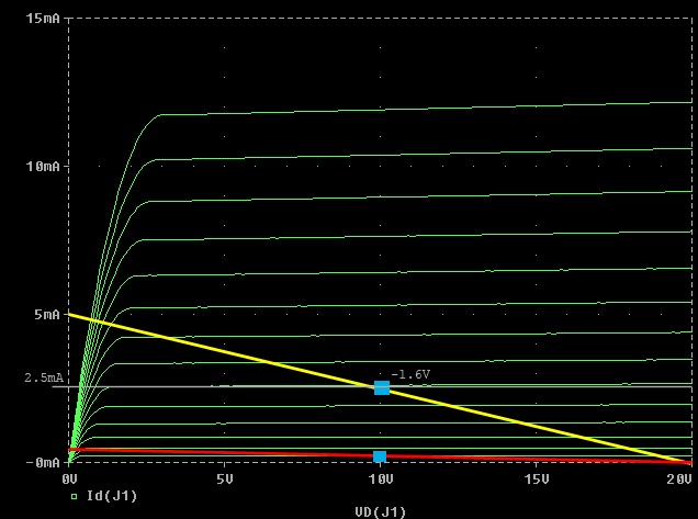
Perhaps this is best explained by looking at the load line for this circuit (stolen from my other thread):

2n3819_bias.jpg


The default load line is in red, and the U87A intended bias point is the blue square on that load line (at about 10V on the drain).  Note that the slope of the load line is set by the drain and source resistors (and NOT the FET!).

But this plot assumes a nominal JFET:  the actual VGS that results in 10V at the drain (with 0.25mA IDS) varies quite a bit from device to device.  One can imagine that if you deleted all of the green lines the load line would not change, however the individual green line (representing the gate-source bias that intersects the blue box) would change from device to device.  This is what setting R11 does:  matches the bias so that the individual JFET idles at the design point.

However the implicit assumption here is that the U87 biasing string depends on the Zener keeping it's node at 24V!  It could be the original JFET's didn't pull much current.  However a modern 2N3819 can range anywhere from 2mA IDSS all the way up to 20mA!  That is a tremendous range for a single topology to cope with!

If you set R11 to maximum, then the drain voltage should be at maximum (the blue box is far to the right).  As you lower R11, the blue box will move along the red line to the left, and drain voltage should decrease as the idle current increases.  As R11 approaches zero the JFET will pinch-off and then the drain voltage will rapidly rise back up.

If you don't see this, then something else isn't correct in the wiring.

If you happen to have devices that have very high IDSS, then you won't be able to make R11 large enough with a 10K pot to move the idle current down into the intended range, because the device will be pulling too much current and dropping all of your voltage across R17!  If you take my plot, and move the top-most line (VGS=0V) up to 20mA (on my plot, it's about 12mA), you'll see that in order to drop the current back down to 0.25mA you'll need perhaps 4V gate-to-source bias, which would be 4V/0.25mA = 16Kohm!

Do you have perhaps a 25K pot to put in place?  Or you could also add a 10K resistor in series with the pot of you can perform the gymnastics on the board with your soldering iron.  I would also test 10 JFET's for IDSS and pick one that's on the lower end of the spectrum.

Hope that makes sense.
 
Matador,
Thanks again for another insightful post.  it will take me a little while to fully comprehend all this info, but quickly can I ask - what's the procedure for checking a fet's IDSS?  I can use a digital multimeter?

thanks.


Matador said:
wthrelfall said:
Matador

I dropped R17 so I now have 23.5 volts at the zener (i can't get it exactly to 24v as I don't have a large range of resistors).  doesn't the voltage at R12 depend on the R11 value?  I mean as soon as I adjust R11 to bias the fet then R12 just tracks this voltage from the fet drain.  so I don't understand how I can get R12 to produce 21v if I'm going to then adjust R11 to bring the fet drain (and therefore R12) back to 10.5v.?
I'm clearly no expert when it comes to electronics but it seems for such a simple small circuit this is proving to be very difficult!

The entire string of voltages depends on the Q point of the JFET.

Perhaps this is best explained by looking at the load line for this circuit (stolen from my other thread):

2n3819_bias.jpg


The default load line is in red, and the U87A intended bias point is the blue square on that load line (at about 10V on the drain).  Note that the slope of the load line is set by the drain and source resistors (and NOT the FET!).

But this plot assumes a nominal JFET:  the actual VGS that results in 10V at the drain (with 0.25mA IDS) varies quite a bit from device to device.  One can imagine that if you deleted all of the green lines the load line would not change, however the individual green line (representing the gate-source bias that intersects the blue box) would change from device to device.  This is what setting R11 does:  matches the bias so that the individual JFET idles at the design point.

However the implicit assumption here is that the U87 biasing string depends on the Zener keeping it's node at 24V!  It could be the original JFET's didn't pull much current.  However a modern 2N3819 can range anywhere from 2mA IDSS all the way up to 20mA!  That is a tremendous range for a single topology to cope with!

If you set R11 to maximum, then the drain voltage should be at maximum (the blue box is far to the right).  As you lower R11, the blue box will move along the red line to the left, and drain voltage should decrease as the idle current increases.  As R11 approaches zero the JFET will pinch-off and then the drain voltage will rapidly rise back up.

If you don't see this, then something else isn't correct in the wiring.

If you happen to have devices that have very high IDSS, then you won't be able to make R11 large enough with a 10K pot to move the idle current down into the intended range, because the device will be pulling too much current and dropping all of your voltage across R17!  If you take my plot, and move the top-most line (VGS=0V) up to 20mA (on my plot, it's about 12mA), you'll see that in order to drop the current back down to 0.25mA you'll need perhaps 4V gate-to-source bias, which would be 4V/0.25mA = 16Kohm!

Do you have perhaps a 25K pot to put in place?  Or you could also add a 10K resistor in series with the pot of you can perform the gymnastics on the board with your soldering iron.  I would also test 10 JFET's for IDSS and pick one that's on the lower end of the spectrum.

Hope that makes sense.
 
Put your DMM in current measuring mode.  Take a Jfet, short gate and source together, and connect to negative terminal of a 9V battery.  Connect one DMM probe to the drain, the other to the positive 9V battery terminal.  You should be able to read the IDSS on the meter.

If your meter can't measure current, then put a 10 ohm resistor (measure it first!) between the drain and the positive battery terminal, then read the voltage drop across the resistor and divide the voltage by the resistance you measured.
 
Thanks Matador for your resourcefullness it very appreciated,  i guess stating that the FET drain should be set at 10.5V it is not a good thing,  like you said it is not all fet that will bias properly into those conditions ,  in my case problably luck i had those 3 FET ending up at the same voltage and idle current when set about there that is probably why i stated the 10.5V adjustments a bit to soon.

i have tried different method the scope the THD method and they would relate pretty well , i did include in the BOM a 25K pot for bias adjustment so there should be some margin there to set those conditions.

but i have to say that my prefered method is to inject a signal trough big RT and SW pad a 1K sine tone and while tweaking the pot i could easilly hear when the FET opens and distorts when it barely opens, i also could relate the behavior of the FET as i tweak the Pot and make sure everything is set properly , i encourage new builder to use the 1K tone method with the room capture software for a minimum thd  past the opening point as this method can be related to our earing it never missed for me,

again this is great info and i still learning great stuff there.
Dan,


Hi matador and Dany,

I've been reading with interest, but sadly I am unable to follow matador's post explaining the fet biasing theory, I'm afraid I just don't have a great understanding of mathematical theory - I'm a cycle mechanic, so I guess it's a bit like when I try to explain to my customers how the gears on a bike work, and they look at me blankly and scratch their heads  ;)  Yes, i've built a few mic pre's and compressors, but mostly kits, so gives you an idea of my level of (in) competence!


But I did manage to measure my 3 fet's.  they were 11.4ma, 10ma & 9.7ma.  Not sure if these figures are higher than 'normal'?  anyway, I installed the 9.7ma fet, and put all my resistors back to the original values specified on the BOM.  This time I installed a 50k pot at R11, and following matador's guidelines, I was able to verify that while reducing the resistance from maximum to minimum, the fet behaved as expected (with the sudden rise near the lowest resistance).  With the drain reading around 10.5v, the pot was giving 5K of resistance, and I'm getting 18.3v at the zener.  I swapped the pot out for a 5k1 resistor and tested the mic, and yes it sounds alot better, actually pretty good.  Signal is low, needs tons of gain for a decent level.  I also did as Dany asked and put a 10k resistor at R11 and tested it.  sounds pretty much the same as the 5k1, but the zener is getting over 20v.

I guess what is confusing me most is that the voltage's i'm getting are dramatically different from what Dany has measured on his.  24v at the zener - is this vitally important?  I know, it's got to do with the fet bias, just can't get my head around it.

I would like to attempt feeding a tone to the mic, but would need clearer instructions dany..

thanks for your patience guys  :-[


Matador said:
Put your DMM in current measuring mode.  Take a Jfet, short gate and source together, and connect to negative terminal of a 9V battery.  Connect one DMM probe to the drain, the other to the positive 9V battery terminal.  You should be able to read the IDSS on the meter.

If your meter can't measure current, then put a 10 ohm resistor (measure it first!) between the drain and the positive battery terminal, then read the voltage drop across the resistor and divide the voltage by the resistance you measured.
 
wthrelfall said:
I guess what is confusing me most is that the voltage's i'm getting are dramatically different from what Dany has measured on his.  24v at the zener - is this vitally important?  I know, it's got to do with the fet bias, just can't get my head around it.

What is your source of phantom power? there's a chance it's not delivering enough power, most mics that require phantom can make do with such a wide range of voltage that the phantom power coming from you mic pre may not be exactly 48V to begin with.
 
benlindell said:
wthrelfall said:
I guess what is confusing me most is that the voltage's i'm getting are dramatically different from what Dany has measured on his.  24v at the zener - is this vitally important?  I know, it's got to do with the fet bias, just can't get my head around it.

What is your source of phantom power? there's a chance it's not delivering enough power, most mics that require phantom can make do with such a wide range of voltage that the phantom power coming from you mic pre may not be exactly 48V to begin with.

47v
 
wthrelfall said:
But I did manage to measure my 3 fet's.  they were 11.4ma, 10ma & 9.7ma.  Not sure if these figures are higher than 'normal'?  anyway, I installed the 9.7ma fet, and put all my resistors back to the original values specified on the BOM.  This time I installed a 50k pot at R11, and following matador's guidelines, I was able to verify that while reducing the resistance from maximum to minimum, the fet behaved as expected (with the sudden rise near the lowest resistance).  With the drain reading around 10.5v, the pot was giving 5K of resistance, and I'm getting 18.3v at the zener.  I swapped the pot out for a 5k1 resistor and tested the mic, and yes it sounds alot better, actually pretty good.  Signal is low, needs tons of gain for a decent level.  I also did as Dany asked and put a 10k resistor at R11 and tested it.  sounds pretty much the same as the 5k1, but the zener is getting over 20v.

You are very close!  The next step is replace R17 with a 50K pot, and start reducing it until the Zener voltage reaches 24V.  You shouldn't see a lot of modulation of the drain voltage, however your output swing before distortion will be better (assume a fixed 10.5V drain value for the chosen bias!).

The 10.5V value is not sacrosanct:  it was chosen basically because it's exactly half of 21V, which on the original U87 was selected as the "VDD" value.  For the JFET's being used, you aren't reaching 21V, so 10.5V is no longer "optimum", based solely on signal swing capability.

All of those currents you measured were in the datasheet ballpark of roughly middle between 2mA and 20mA, so don't worry too much.

As for gain:  what transformer did you end up using?  The gain of the circuit is (roughly) -R12/R11, which for R12=47K and R11 =5K is about 10.  And the step-down transformer will throw part of that back away:  for example a 10:1 Cinemag CM-2480 will reduce the overall gain of the circuit down to unity.  The original Neumann transformer was (I believe 7:1) which means the overall gain is only 3dB.  So unless you are close miking stuff with hot transients the mike is going to be on the quiet side.
 
Anyone has any info on what the Aurycle transfomer is it has never been intented for this project anywhay but
if it has a ratio of 15:1 that would not help any cause here.

 
Hi Wthrelfall ,  i hope this can help referencing things, i did a measurement here with original component value and without the FET installed  and No transformer installed and no capsule installed and No R11 installed and my reading at the Drain pad is 22.67V same as on the top of the Zener can you verify that,  if you dont have that then something went wrong during stuffing. i measure the FET i did installed for IDss (Thanks to Matador )
and i have a 10.4ma IDss,

Hope this helps,
Dany,


poctop said:
Anyone has any info on what the Aurycle transfomer is it has never been intented for this project anywhay but
if it has a ratio of 15:1 that would not help any cause here.

The Aurycle site contradicts itself:  it says 2:1 (which makes sense with a PNP follower in that circuit).  But another page says 10:1 so who knows....
 
Tuning Pointers. Hope this helps :)

with nothing connected to the  Front Capsule nor Rear Capsule ( important )For the sine Tone Method and THD Method : use the big RT and SW Pad on the board,  RT + ,SW -
feed it 0db (0.775VAC) at 1Khz and tweak the pot , if using your Daw as sine tone ,you should be able to hear what come from the mike with headphone or something you need to be able to ear separtely what come from the mike,  tweak the pot fully in 1 way and then fully the other way you should ear the sounds come louder and then get to almost dissapear, what you need to do is to tweak just after it becomes louder and there is no more Fizz in the sounds, you will clearly ear fizzing when the FET opens, just a bit past this point is the good approximative Bias, if you go too Far the Signal will becomes fizzy again but more subtile past this point.( easier to see on a scope) At this point the method is the same for using the Room capture demo software with the THD Meter you only use the THD Meter as an indicator , when the FET opens the Meter goes up at near 25-30% THD so you can clearly see what happening the more you tweak past the opening point the Less THD on the Meter until your reach about 0.4% thd that is fine. if you go too far the THD will slowly rise backup as the fizz in the sounds as the sine symmetry seen in a scope meter, doing it a couple of times is good pratice and you can actually verify your method with the ending drain Voltage if the ending voltage makes sense.

Hope this helps,
Dany,


Latest posts

Back
Top