Neumann Vintage U87 Clone : Build Thread.

GroupDIY Audio Forum

Help Support GroupDIY Audio Forum:

This site may earn a commission from merchant affiliate links, including eBay, Amazon, and others.
The Resistance Matching is in the considerations Excel on the first page of the Thread 0.4% Matching here some from the Docs.

Do you have your mic PCB in a sheilded environement ( Mic body Arround the PCB to GND)  when you do those test  ? the circuit sensitive to RF you will hear it even more with the capsule in ,

Here are from the BOM: 


Attachments

  • i.jpeg
    i.jpeg
    162.8 KB
There some conditions to this project also, as there is not supposed to be chinese component when finished  ;) except for the Body  ???

Dan,
 
Okay, my mic's working great! Checked all the voltages today and they're dead on.

There's only one quirk I can't get my head around: I'm using the Aurycle body, as of now unpainted, and if I over tighten the bottom ring the signal will die. it always comes back when I loosen it a bit, and I can't figure out where it's shorting. No matter how much I play with it I can't get it to cut out unless I tighten that bottom ring. It'll take some playing with I suppose...

Also, if you're using the Aurycle body keep in mind that you have to reverse the wires to the low-cut switch. The pad wires are correct.

As far as the Peluso capsules: be carefull getting them out of the packaging. One of mine slid right out, but the other one required a bit of prying, which ended up with me damaging the backplate. I was planning to use them as cardioid only anyway but it's still a bit of an annoyance.
 
I asked Peluso about the BV11T mentioned in poctop's email, as I was unable to find it on his website. He said it was on the site, and costs $85. The only x-former that fits that description is the BV11P. Is this the transformer I'm looking for?
 
R18 & R19 are an exact match, 2.2k.  I followed the instructions exactly.


Matador said:
wthrelfall said:
measuring from the xlr output.
can't recall the exact measurements, but this was my voltage readings taken earlier
top of L1 - 48.6v
top of L2 - 45.9v
top of R18 - 48.6v
top of R19 - 45v

That doesn't look right:  you should be pulling phantom current equally through R18 and R19, which means the common nodes on the "top" of these resistors should be the same.  This is why R18 and R19 are specified to be closely matched (to within 0.1 ohms or better).

The voltages you show above mean that there is a 2.7V drop across the transformer, which means there is DC current flowing through the secondary, which is going to be 50Hz hum city.

There's only two things that can explain this:  either of R18 or R19 is not the correct 2K21 ohm value, or the secondary may have a short to ground. 

It seems that most of your woes center around this Aurycle iron. ;)  When you disconnect the transformer, do your "top of R18/R19" voltages re-equalize?
 
wthrelfall said:
R18 & R19 are an exact match, 2.2k.  I followed the instructions exactly.

Yeah, I figured as much, given the tremendous difference in voltage.  That really couldn't be explained by a resistor mismatch (of even several hundred ohms), unless you were trying to pull a tremendous amount of current from the phantom supply.

Did you try re-measuring the R18/R19 voltages after the transformer is disconnected?
 
Yes, same voltages with and without the tx..


Matador said:
wthrelfall said:
R18 & R19 are an exact match, 2.2k.  I followed the instructions exactly.

Yeah, I figured as much, given the tremendous difference in voltage.  That really couldn't be explained by a resistor mismatch (of even several hundred ohms), unless you were trying to pull a tremendous amount of current from the phantom supply.

Did you try re-measuring the R18/R19 voltages after the transformer is disconnected?
 
Wthrelfall your initial Voltage that you have posted are fine,  dont forget that we are using a 10% tolerance inductor and some 5% resistor , and the most important is the current divider in 2K2 pair,  my voltage here shows some little difference but are pretty damn close and the mic is working like charm ,  you are all good with what you have for now i think you just need to stick the proper traffo in there and you will  be fine.  keep on the good work.
 
Yeah Dany, I've got a transformer and peluso capsule on order, hopefully it'll make the difference!


poctop said:
Wthrelfall your initial Voltage that you have posted are fine,  dont forget that we are using a 10% tolerance inductor and some 5% resistor , and the most important is the current divider in 2K2 pair,  my voltage here shows some little difference but are pretty damn close and the mic is working like charm ,  you are all good with what you have for now i think you just need to stick the proper traffo in there and you will  be fine.  keep on the good work.
 
The diode you have is 5% also So 22.8V is just Fine, it may vary a little,  22.8 to 25.2V

This are all what you need

top of L1 - 48.6v
top of L2 - 45.9v
top of R18 - 48.6v
top of R19 - 45v
bottom of R17 - 45v
top of R17 - 23.18v
Zener 23.17v
FET drain pad 23.15v
FET source pad 0.089v
top of R12 23.15v
top of R13 42.4v
top of R14 23.14v
top of R8 41.8v

Keep Rockin  8)
 
wthrelfall said:
R18 & R19 are an exact match, 2.2k.  I followed the instructions exactly.


Matador said:
wthrelfall said:
measuring from the xlr output.
can't recall the exact measurements, but this was my voltage readings taken earlier
top of L1 - 48.6v
top of L2 - 45.9v
top of R18 - 48.6v
top of R19 - 45v

That doesn't look right:  you should be pulling phantom current equally through R18 and R19, which means the common nodes on the "top" of these resistors should be the same.  This is why R18 and R19 are specified to be closely matched (to within 0.1 ohms or better).

The voltages you show above mean that there is a 2.7V drop across the transformer, which means there is DC current flowing through the secondary, which is going to be 50Hz hum city.

There's only two things that can explain this:  either of R18 or R19 is not the correct 2K21 ohm value, or the secondary may have a short to ground. 

It seems that most of your woes center around this Aurycle iron. ;)  When you disconnect the transformer, do your "top of R18/R19" voltages re-equalize?


I think i know why you are confused  ;) There is nothing wrong with your Phantom Power , When you say on top of resistor that does not relate onto the top the of R2 in the schematic ,  this is why your are confused , and the board is designed this way. if you are carefull on putting the resistor in the right way ( on the Bigger circle on the PCB) you should have the same voltage on top(top of board) of the 2 inductor 48V ish. And the top (top off the board) of the 2.2K resistor should be a bit diffent because  (top off the board) is actually after the current divider.  as for the regulation the Zener will decide how much is a Voltage drop across R17 it is the remainer of the Zener Differiential,  and Then the 10-15V ish on the Drain has you tweak it and about 20V after the Zener. dont get confused as if the schematics is a map of the boards,

So everything is Correct Voltage Side Wise  :)
Hope this helps ,


Marcocet said:
Okay, my mic's working great! Checked all the voltages today and they're dead on.

There's only one quirk I can't get my head around: I'm using the Aurycle body, as of now unpainted, and if I over tighten the bottom ring the signal will die. it always comes back when I loosen it a bit, and I can't figure out where it's shorting. No matter how much I play with it I can't get it to cut out unless I tighten that bottom ring. It'll take some playing with I suppose...

Also, if you're using the Aurycle body keep in mind that you have to reverse the wires to the low-cut switch. The pad wires are correct.

As far as the Peluso capsules: be carefull getting them out of the packaging. One of mine slid right out, but the other one required a bit of prying, which ended up with me damaging the backplate. I was planning to use them as cardioid only anyway but it's still a bit of an annoyance.


Have you followed the instructions for the potentiomter if you let it in, in certain case you may have to file the edge a bit to make sure you a re not stressing anything in the Aurycle mic ,  i have one here and i can use a boa tool and screw it to death.

Hope this helps,

dan,
 
poctop said:
Have you followed the instructions for the potentiomter if you let it in, in certain case you may have to file the edge a bit to make sure you a re not stressing anything in the Aurycle mic ,  i have one here and i can use a boa tool and screw it to death.

Hope this helps,

dan,

Yeah, the pots have been replaced with resistors and the bodies have been painted so there's no electrical connection except for the edges, but it's still happening. And only on one mic. Super weird, right? I'll check it out more thoroughly today.

-marc alan
 
Marcocet said:
Okay, my mic's working great! Checked all the voltages today and they're dead on.

There's only one quirk I can't get my head around: I'm using the Aurycle body, as of now unpainted, and if I over tighten the bottom ring the signal will die. it always comes back when I loosen it a bit, and I can't figure out where it's shorting. No matter how much I play with it I can't get it to cut out unless I tighten that bottom ring. It'll take some playing with I suppose...

Is it possible tightening it is flexing the support rails, thus flexing the PCB or XLR connector and causing something to become open (as opposed to something shorting)?

A bit wire with a bit of insulation exposed?
 
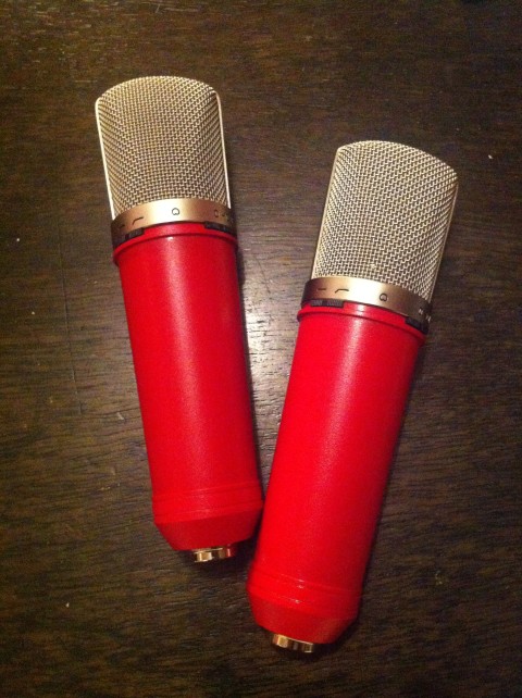
Yep, it's just one of them that's being a problem. I only get to work on the things intermitantly but I should be able to put together a full report on the things soon. For now here's a pic! (Also it's on my new diy blog for the studio. I've built a lot of stuff we use, so I figured it's time to start documenting it. http://strangeweathercustom.wordpress.com

photo-e1332469395496.jpg
 
Marcocet said:
Yep, it's just one of them that's being a problem. I only get to work on the things intermitantly but I should be able to put together a full report on the things soon. For now here's a pic! (Also it's on my new diy blog for the studio. I've built a lot of stuff we use, so I figured it's time to start documenting it. http://strangeweathercustom.wordpress.com

photo-e1332469395496.jpg

this look nice a pair, congrats ,  for the one that squezze you may wnat to stilck your DMV on pin 1 and 2 or 3 and stick it to the XLR while yo are tightening it you may find if you have a short at a certain point when squezzing , hope this helps,
Again thanks for sharing  ;D
 

Latest posts

Back
Top