Neumann Vintage U87 Clone : Build Thread.

GroupDIY Audio Forum

Help Support GroupDIY Audio Forum:

This site may earn a commission from merchant affiliate links, including eBay, Amazon, and others.
Ok out of curiosity, because I just solved my hiss problem, and the soldering iron was warm, I tried Hank's method of reversing the transformer leads.
Definitely louder!

Can anyone comment on this? Is the info on the transformer sheet wrong? or are we just wiring it backwards and have changed the output impedance now. Please help :)

I hope it's right cuz this mic sounds great now. I though I just disliked the capsule!
 
"It should be black wires on the capsule side and yellow on the XLR side!"

  Whoa... thanks for that! It added at least 10db here too!

"The vintage one does not have the caps (C16 and 17) nor the inductors at the XLR. (as in the U87i?) Why were these there anyway? "

  AFAIK, those were added around 1980 to minimize RF interference. You could take them out and jumper ONLY the inductors if you wanted to imitate the earlier versions.

  Don't know about the other differences you see. I seem to remember reading there were many variants of the circuit early on. As you may know http://www.recordinghacks.com/microphones  is a good resource for this kind of stuff...

Regards,

Dave McKenna

 
Hank Dussen said:
OK, I did some more tests.
I did have 40v on the backplate of the capsule after all. There was just something wrong with my DDM.
After double (triple) checking all the components I started comparing my mic to the vintage U87 I borrowed.
This lead me to the transformer. I was pretty sure I hooked it up correct, yellow wires on the cap side, black wires on the XLR side.
Just as on the AMI site. http://www.tab-funkenwerk.com/id133.html
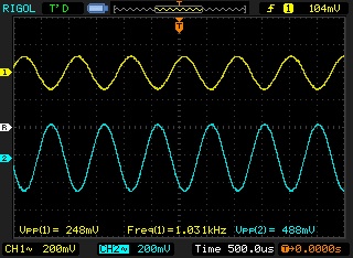
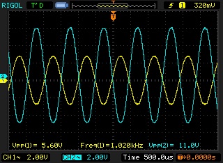
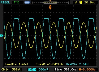
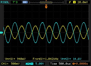
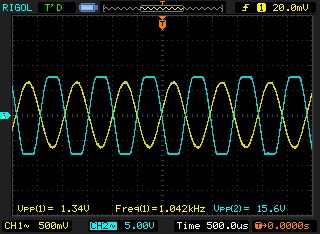
Nevertheless I decided to reverse it and, bang, there was my 15dB of gain!
It should be black wires on the capsule side and yellow on the XLR side!
(at least with my transformer)

My mic levels perfectly together with the vintage U87 now!

But what's more I compared all the components and it appeared there are some small differences between mine and the vintage U87:

The vintage one does not have the caps (C16 and 17) nor the inductors at the XLR. (as in the U87i?) Why were these there anyway?
C6 has the marking 820 on it. But 820pF seems way too high! Maybe it's 82pF?
R9 is 1k2 instead of 6k8
C5 is 0,015uF instead of 0,01uF
R2 is 330k instead of 150k
R11 is 4k7 and there 6,85v @ FET drain, 1,25v @ FET source

In the circuit I measure 58R between the primaries (capsule side) of the transformer and 1k2 at the secondaries.
With the AMI transformer that's 22R and 435R, which seems quite a difference.

Does anyone have some toughts on these differences? They don't seem to be that important but nevertheless they must have done it for a reason.
They do seem to be original. Not something that was altered later.


Pieter
i really would like to see proper dc reading of the transformer"primary" and "secondary" in is final position for sure if it make sense, i always took an habit of checking my tranformer before i put them in ,  i have seen some open winding and other sort of stuff too.. would be a very long story, even had a bad T67 that is why i included a troublshooting tips in the U67 build folder,

as per the difference it might be totally normal ,  this design is based on 1972 based on revision 16 ,  you can actually see it on the transformer it says circuit diagram 16 or 21 or lower than that if much older, as in the revision 21 from 1980 they included that extraRF filtering at the input , this is the only thing that has been implemented to the revision 16 hence the name U1621 ,
for the rest it is all version 16 from 1972 with 24V regulation,  all of those version staying in the Vintage circuit category obviously.

if you have a lower revision than 16 that would be it, 


I am really curious to find out about this transformer story because some people reported this problem also , and it could have been a wrong info or labeling in regards to the t13  , 

The drain Voltage you report seems diefferent and this might be because the SK107 type verify if that it is the one that you have in your mic,
bias lower voltage than the 3819,
My bet is that is the transformer is backward then you would have 1:10  but the driving impedance of the cicruit would make it to sound very mushy is it the case ?

Let me know how you progress,  i really would like to see an explanation for all this  :)
Hope this helps,
Dan,
 
poctop said:
I am really curious to find out about this transformer story because some people reported this problem also , and it could have been a wrong info or labeling in regards to the t13  , 

I'm guessing AMI info sheet is wrong...
Right now the levels of the 2 mics are within 1dB. And they really sound very alike.

poctop said:
The drain Voltage you report seems diefferent and this might be because the SK107 type verify if that it is the one that you have in your mic,
bias lower voltage than the 3819,
My bet is that is the transformer is backward then you would have 1:10  but the driving impedance of the cicruit would make it to sound very mushy is it the case ?

It's a 2N3819 FET...

I didn't do any in depth comparisons but it didn't sound bad with the transformer backwards. Just lower in output.
Maybe the lower resistance between the primaries and secondaries of the AMI transformer have something to do with this?

 
Hank Dussen said:
poctop said:
I am really curious to find out about this transformer story because some people reported this problem also , and it could have been a wrong info or labeling in regards to the t13  , 

I'm guessing AMI info sheet is wrong...
Right now the levels of the 2 mics are within 1dB. And they really sound very alike.

poctop said:
The drain Voltage you report seems diefferent and this might be because the SK107 type verify if that it is the one that you have in your mic,
bias lower voltage than the 3819,
My bet is that is the transformer is backward then you would have 1:10  but the driving impedance of the cicruit would make it to sound very mushy is it the case ?

It's a 2N3819 FET...

I didn't do any in depth comparisons but it didn't sound bad with the transformer backwards. Just lower in output.
Maybe the lower resistance between the primaries and secondaries of the AMI transformer have something to do with this?

For the bias voltage it may very well be , as each Fet is different and the bias is the bias ie what you see on the scope is what you get ,  normally it goes from 7 to 13 so a bit on the low side but not to worry.
could you measure the dc resitance of the transformer the way you use it as primary secondary that would give a hint ,

I'm guessing AMI info sheet is wrong...
Right now the levels of the 2 mics are within 1dB. And they really sound very alike.
That is a good news  :)
Best,
Dan,
 
IMPORTANT NEWS,  

I actually have one unused T13 here and it reads 22R Yellow and 420R black ,

So the information on AMI website is in the need to be confrimed because my transformer color code here would not work as connected like the AMI website reference ,  WOW  :eek:  this might be the cause for all of you that had problem with lower output microphone,  would seems that some of the transformer are actually the wrong side outhere,

I have to say that i feel so much relieved of this findings, 

I might have to say to all of those that had this problem to check it out because this will solve the issue garanteed,
and you will be able to finally enjoy the mic as intended at the first place,

i will notify Oliver as well , please post on this thread if you have an inverted color coded transformer ,


Best,
Dan,
 
Another witness here!  8)

I have a Poctop U87 with low output (which I bought from another member cheap because of that) and was waiting for some more 2N3819 to find one with lower IDSS.

Just checked the DC resistance on the AMI T13 transformer and got similar readings as Dan:
Black = 437Ohms and Yellow = 22Ohms

After resoldering the mic got +10dBs more!

Thanks Pieter for clarifying this, I guess paint by numbers isn't that easy after all!  ;)


Matador said:
Operated 1:10 I'm surprised the mike was usable at all!  Like 97% of the signal would be thrown away.

Yep this is a very tough mic.  8) :eek:
D.
 
Hello gents (and ladies?),

I had the same issue with my build using the T13 transformer-ultra lowish level,not really usable for most of my recordings.
Have put it on the shelf for a while because my real job got me back.
I often thought of reversing primary to secondary one day-if I would ever have the nerves,thinking of it as a say "last chance" to get lucky with it,hahahaha.......
Dan was so kind to keep me posted all the time,and yesterday he sent me a mail saying that there is something going on in the thread concerning the T13.
I had the notification on all the time,and one post triggered me to get hands on this at the weekend (I think it was 2 or 3 days ago).

And the award goes to:PIETER ("Hank Dussen")-HOOOOORRRRRRRAAAAAAAAYYYYYYYYY!
You´re the winner of two brandnew and idss-checked fets! ;D ;D ;D ;D ;D ;D ;D ;D ;D

So I went to swap the wires (this takes some 3 minutes or so),took it to our studios and did the same comparisons I had some months ago,again using SPL Gainstations (a pretty close matched pair) with just the clean gain on.Matched levels in ProTools,read the pointer positions and then swapped mics and pres to confirm a correct reading from them again.

I can confirm absolutely correct levels now,my readings have been a 35dB and 46dB of gain pot positions which equal -11db difference to an U87Ai!!!This is exactly what i wanted to see all the time-SPOT ON!

What a relief that was!

Will not explain it soundwise again,I did it before (Yes,it sounds like a Neumann!).

Thanks to all you guys for putting in so much work here,the result is outstanding.

I´m so happy having my "baby" up and running as I wanted to have it now,this definetely made my day!
It was a long and hard journey,some of you around here might remember how much trouble I had even with sourcing the T13s.

Last but not least a big THANK YOU to my (may I say that) friend DAN,CHAPEAU BAS!
You made a dream come true for us.....

My deepest respect is with you!

Your BOTSF Udo :D

Oh,here´s a pic for those who are unsure of the now correctly working T13 wiring:


Attachments

  • T13 corrected wiring 3.JPG
    T13 corrected wiring 3.JPG
    303.2 KB
kante1603 said:
And the award goes to:PIETER ("Hank Dussen")-HOOOOORRRRRRRAAAAAAAAYYYYYYYYY!
You´re the winner of two brandnew and idss-checked fets! ;D ;D ;D ;D ;D ;D ;D ;D ;D

What an honor to win this brand new award! ;)
And that on my birthday!!!!! (36 today)

Let this be my modest contribution to this great project on this great forum that has given me so much!

Pieter
 
OK transformer out of circuit, 427 ohms black wires, 21.8 ohm yellow wires.
Re-checked bias to make sure it hadn't drifted and it's still right on.
Mic working perfectly aside from the fact that I still have not fixed the backwards functioning low cut switch.

I'll get to that this weekend :)

Thanks Pieter for pointing this out. You've made me love this mic again :)


Ken
 
kpearsall said:
Mic working perfectly aside from the fact that I still have not fixed the backwards functioning low cut switch.

I'll get to that this weekend :)
Hi Ken,

do you need help with that?If it's a normal toggle switch you only need to swap the outer wire to the opposite outer side of the switch,done.

Cheers and have fun,

Udo.
 
well that's three seconds more than I had yesterday  ;D

It's done now. and a lot of other things that I had to do. It's been a productive morning!


Ken
 
Here are some more biasing pictures with 2N3819 and 2SK170BL JFET's.

Most of the 2N3819's I have are in the 9 to 11 mA range for IDSS range.  I selected one that measures 9.23mA.  Drain resistance is 46.7kOhm, and source resistance is set to 20K and is adjustable.  Signal is injected at the gate, which has a 1MOhm resistor to ground as well.

Here is the first plot.  Yellow is the signal generator, and blue is the AC coupled drain signal.

u87_bias1.jpg


You can see that the peak-to-peak amplitude going in is about 250mV, and the output amplitude is 488mV.  This is a gain of just under 2.

If I dial up the input amplitude up to the limit of my signal generator, the signal still looks fine:

u87_bias2.jpg


I cannot get symmetrical clipping on this JFET because a) my signal generator doesn't go high enough, and b) the source resistor is too low.

Let's try a 2SK170:  the onset of positive clipping happens much faster as a function of amplitude.  This JFET has a lot more gain!

u87_bias4.jpg


So we start dialing down the source resistance from 20K until the top of the waveform recovers back to a round shape.  Then we increase the signal amplitude some more and repeat a few more times.

u87_bias5.jpg


At this point, increasing the input amplitude more causes both sides of the waveform to clip:

u87_bias6.jpg


Based on the previous scope shots, the gain is about 15, or about 7 times that of the 2N3819.  Final source resistance was about 2.5K.

So we can see we can get a lot more gain with a 2SK170, however input amplitude before clipping is reduced by the same factor that gain is increased.  In other words, the 2N3819 could take over 3V input without clipping, whereas this particular 2SK170 was limited to roughly 500mV.

Neither of these is right or wrong:  if you do a lot of close miking and have external preamps that have tons of gain to spare, then the 2N3819 will give you the most faithful reproduction of the capsule without much chance of clipping any of the stages.  If you do a lot of distance and/or room miking and are struggling to get enough gain, then the 2SK170 works better.
 
Back
Top