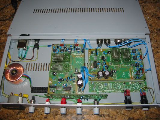
New 'ultimate' SSL buss comp clone ;-)

GroupDIY Audio Forum

Help Support GroupDIY Audio Forum:

This site may earn a commission from merchant affiliate links, including eBay, Amazon, and others.
OK, I got the point. Everything double.

I haven't read the full thread yet but I think I got the point on the advantages by using the modes.

Is there any chance to hear some AB sound test files? I have all what I need for this DIY but the
sound file to get me started :green:
 
well what i'm wondering about this *amazing* new version we've got here,

what is the circuit for using multiple SIL THAT's on a 202 sized pcb?

man this baby just begs to be in a big case with the boards at the far right stacked vertically to the side of the case, way way way away from the power stuff, which is on the far right.

then use all the extra front panel space for 2 GR meters and two buffered output VU's.

and big, pure-path, knobs.

;]
 
sort of along the lines of enthalpy's question... as i have 4 202xts and had planned on 2 GSSLs, but now I think 1 GSSL and one UltimateSSL. thats using 2181's on the sidechain and 202s on the signal.

Why use the 202 in the first place... was it distortion or "response, sound-i.e magic, that certain something etc."? seems from reading various threads that it was actually a bit of distortion that gives the 202 that happy snappy sound.

I'm trying to sort out what may be the better option here.
Clearly i'm seeking opinion and not analysis, but please do tell.

what to do...
To use a single 202 on this box and skip the differential nulling, keeping that 202x sound.

Or

use the gyraf 2181 circuits on both boards and let the differential nulling do its distortion reduction thing... so it would be super clean.


If i understand the differential nulling then using 202xs on the left board and 2181s on the would just be stupid, though I did consider it for a few minutes.

Kelly

schemo for multi sil vca is here.

http://www.groupdiy.com/index.php?topic=13713&highlight=202+vca
 
[quote author="SSLtech"]

Basically it's more like the console buss compressor in one significant way. Jakob's version uses a summed-mono signal which is fed to a single sidechain VCA. phase, polarity and balance affect the detector output. In the console version, two sidechain VCAs feed two detectors, and the higher output is used. Balance, polarity and phase differences are ignored.

Keith :guinness:[/quote]

What does this mean " The HIGHER output is used"? :?

I had just about everything loaded into my brain about this project until I read this line... I thought the channels in the real SSL stayed separated fully left & right the whole time :roll: including sidechains & returns to the main VCA's.
... this statement makes me think they join back together after the sidechain somehow or am I reading it wrong?

Thanks,
Kevin
 
[quote author="matthias"]no,

in the original design the control voltages are summed before the timing circuitry... these are dc voltages, so the highest voltage controls the vca..[/quote]

Thanks... it is hard to believe that the CV is still shared by the main VCA's & that these subtle changes can make THAT much of a difference :shock: I do know that I do not find my GSSL usable on my Stereo mix buss but works well on a parallel drum buss.

I have my boards about 80% loaded & working on the case now :green:

So, the ONLY parts on the second control PCB are the RATIO resistors???

Can I still use the PCB Lorlin switches & attatch them to the main front panel PCB?
(I'll just attatch wires to one of the other polls on the RATIO to connect to the 2nd control board - they don't seem to connect to anything else)

Sorry for the dumb questions... I just want to make sure.

Thanks,
Kevin
 
khstudio said:
[quote author="matthias"]
So, the ONLY parts on the second control PCB are the RATIO resistors???

& 1 diode from memory

Can I still use the PCB Lorlin switches & attatch them to the main front panel PCB?
(I'll just attatch wires to one of the other polls on the RATIO to connect to the 2nd control board - they don't seem to connect to anything else.

Yes
 
[quote="mikep]
wayne/keith, How is the true power summing mod coming along? I wonder if this could be fit on a genuine 384? one mod I had in mind, that won't work with a Gssl but will with your "ultimate version", is to lowpass filter the sidechain signal cross-coupling. so that high frequencies, or the fast components of the CV signal, are essentially unlinked. I can explain the reason for this. In mastering I compress unlinked all the time, usually with a 33609 (everthing is stepped, so it is easy to match L/R). with very small amounts of GR, "image shift" is not a real concern. (I don't know why people get so bent out of shape over this, probably because they have never tried it for themselves and LISTENED.) a subtle narrowing of the image, however is a problem. rule of thumb: the faster the time constants, the better it sounds unlinked. IMO the only tradeoff is that when running linked, the center can be more solid. it is primarily a low-end thing. Sometimes I use this to my advantage, if I have the urge to cut a little low end with an EQ, sometimes the unlinked comp gets you at least partway there "for free". but it would be nice to have the wide image AND the solid lows in the center.

mike p[/quote]


I've been a broadcast engineer for 20+ years, and have done my share of experimenting with commercial audio processors, designing several processors, and experimenting with many different types of topologies, and when "strapping" the channels is required, the "or", or greater of the 2 channels control always sounds best, keeping the loudness ratio between the channels equal, and providing the most solid sound.

I've used the That chip sets in several custom designs and have recently played with power summing. I like it better than the arithmetic sum into one detector, but I'm not sure I like it better than "or-ing".

If you want to have fast transients handled unstrapped, you have two options; 1) install a second set of detecors to handle this 2) modify the "or-ing" connection and timing network so that each channel's detector feeds a "fast" timing section, as well as "or-ing" to a "slow" timing section. I've experimented with this in the past, and it works well.

The Aphex compellor 320a uses a similar scheme, where you can strap the 2 channels, strap the slow leveler only, leaving the faster compressor unstrapped, or unstrap everything.

For a quick and dirty check, you could take unstrapped detectors, and connect a resistor between the timing circuits, using a value that would charge the opposite channels timing cap with an average speed value. i.e., if the cap is a 1uF, and your attack time is 1-10ms, use a 22-47kohm resistor for a 22-50ms attack. Average signals will still respond to the "greater of the two, while transients will be handled by each individual channel's detector.

Just for fun I'll throw this into the mix; why not provide a sum and difference path, and compress the M+S separately, like the good ol' Fairchild 670 did?
 
Good idea. I did draw up a simple M/S chip-based encoder/decoder... Nobody ever seemed to take it up though.

I have to say that I too have found that the "Greater of two" ('Oxford' mode) can more often sound better (in what is only my opinion, of course) across a whole program mix than "arithmetical sum" ('Gyraf'/'Aarhus' mode)...

However, Within a mix, when there will be other things around it with a largely constant level (heavily compressed bass, guitars, pad keyboards, 'blocked' backing vocals etcetera) if you 'smash' a drumkit in stereo, I have found that the 'Oxford' mode can occasionally force a (gratuitous example) hard-panned floortom to excessively 'duck' the channel which doesn't have the information... basically it doesn't 'average' the level as well as the 'Aarhus' mode does. -Of course, power summing may even be better yet, but I've definately found rather more instances where the 'Aarhus' mode is preferred on sub-mix compression, yet 'Oxford' mode wins out on the whole mix.

A local studio has even asked me if I can look into converting their in-console SSL master compressor to switch between modes... I'm looking into it at the moment... right now it's more a question of whether I can find the time!

I like the suggestion of 'partial link' but I'm slightly concerned that a partial unlink would pull 'partly-panned' signals more toward the center, since it would equalise the inter-channel signal levels more than the other methods discussed thus far. -Still, it's definately worthy of consideration.

-On the Compellor, was it the buton marked "stereo enhance" which you'r e referring to? -I usually left it in, but didn't ever actually notice a particularly dramatic effect... We had the early version I think (if there was more than one... certainly it was purchased new in 1984...)

Keith
 
HELP!

I should have my unit finished tonite.

I'm getting ready to make all the connections but I stopped to look at all the PCB layouts & schematic & I feel there is some MISSING OR WRONG info in the instructions :?

The instructions say :
9. Connect “C” & “D” on the slave main pcb to “C” & “D” on the slave switch pcb.
C does NOT connect to anything on the Slave switch PCB:!: (unless there are a few JUMPERS you guys didn't mention???)

D doesn't make sense either... going to resistors that are NOT installed on the slave switch PCB :?:

Also, the threshold pot seems to interact with the ratio control & is also not used on the slave switch PCB... so how does that work ?:oops:

6.The +12v & -12v points on both switch pcb.
These points are not clearly marked... where are they???


Thanks,
Kevin
 
[quote author="radiance"]I thought those "D" , "C" etc. point where only to be found on the latest schematic, not on the pcb itself...[/quote]

WRONG. Look again.

They are clearly marked on the PCB & Layout to show which pins go where.

A Larger version of this pic & especially detailed info of which pins are being used on the slave switch pcb & WHERE they are going would help... aslo any jjumpers - if any.

4kcloneinside.jpg


Kevin
 

Latest posts

Back
Top