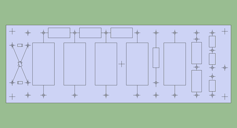
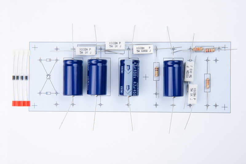
Ok. . .when last i updated, I was a bit depressed because I just messed up my mic build. This time, there are mental errors that happened again on my turret board layout, but minor spacing ones that do not effect this build as all of the main resistors along the top side are changed to chassis-mounted types and will not connect directly to the turret board. So, this thread is not turning out the way i had hoped which would be a nice, clean step-by-step walk through of the mk47 tube microphone build, but DIY is sometimes a bit messy especially on the first try for reading/transferring a schematic and point-to-point construction. Hopefully, there will still be enough concise information here to still help a few people along.
So, with new supplies in hand, I am ready to do better on the 2nd try. Note the G10 board is a different color than the last one. A bit less bright green which is unfortunate for pictures, but the important thing is I purchased enough to start over again if i mess this one up too!
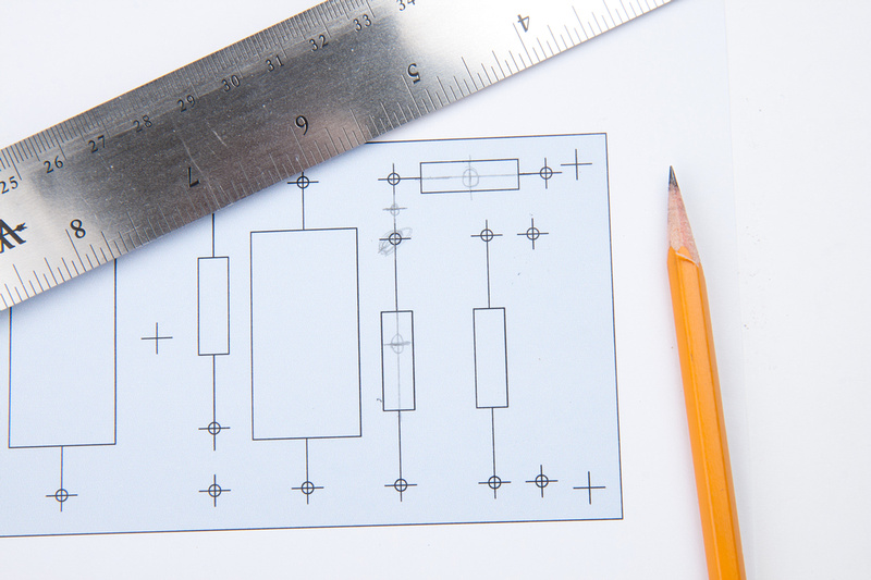
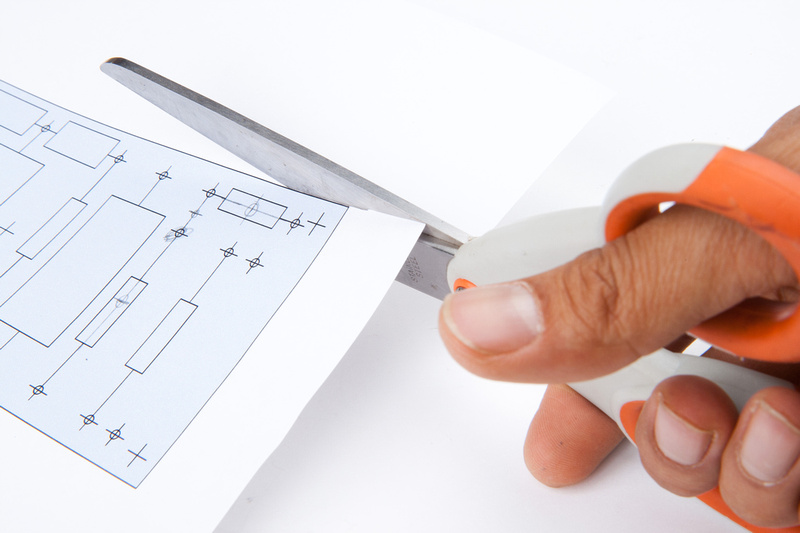
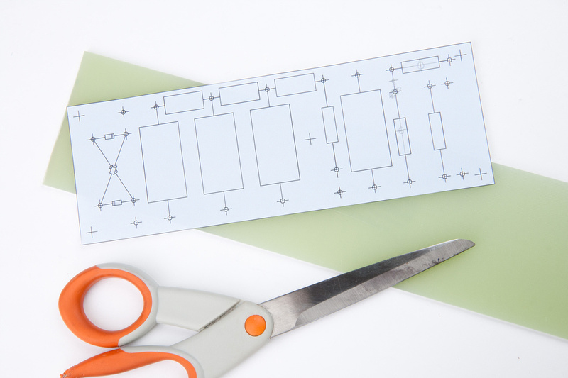
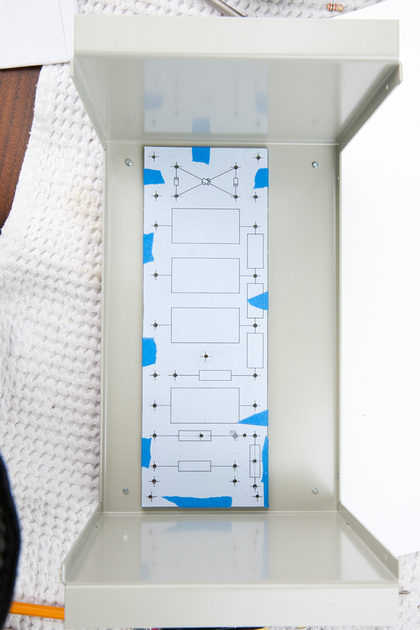
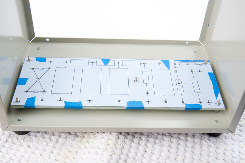
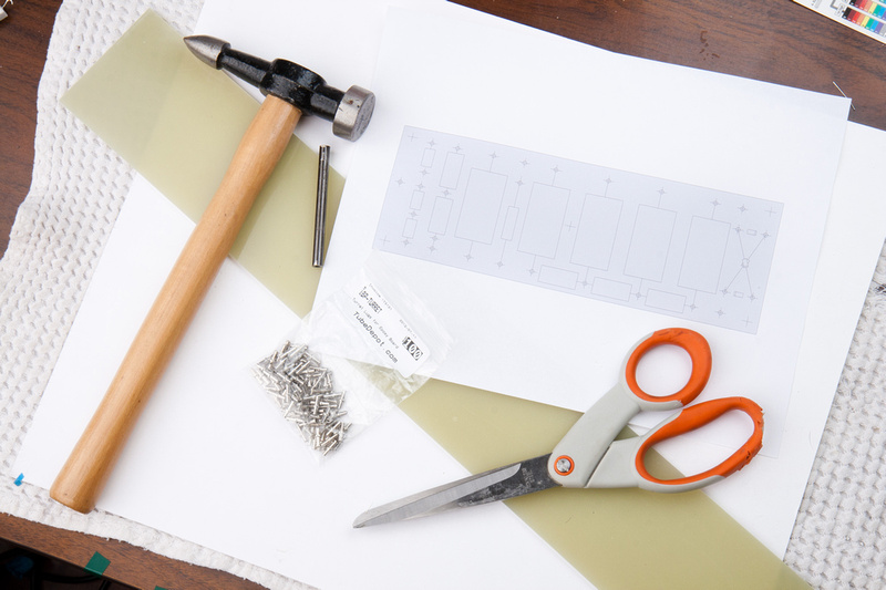
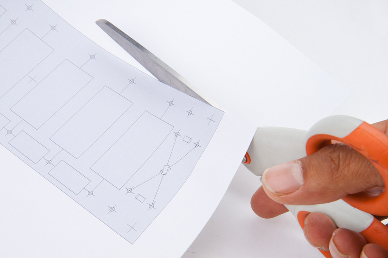
Next, I carefully cut my new template to size.
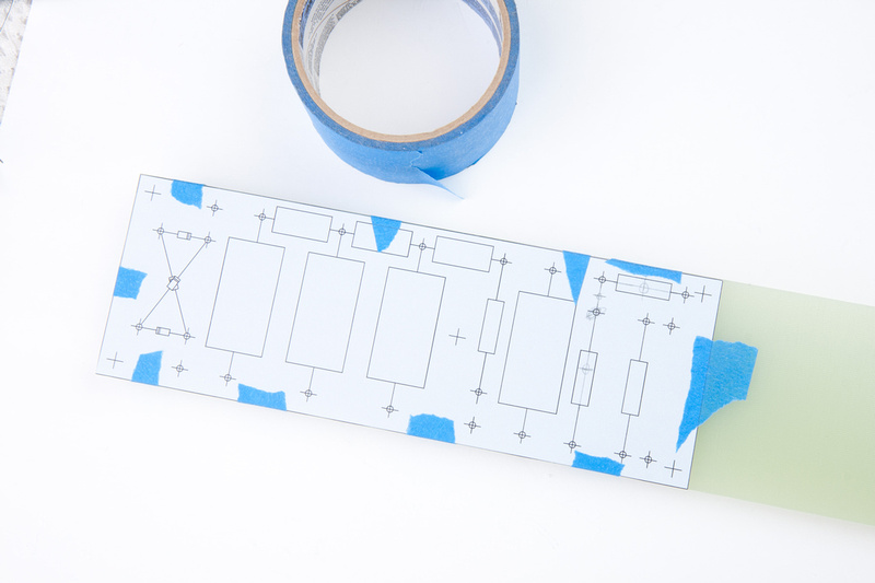
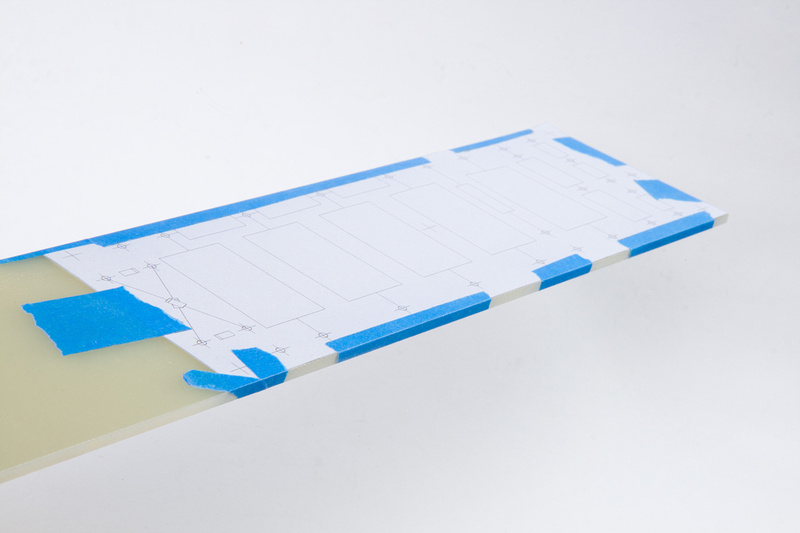
And tape securely to the G10 board.
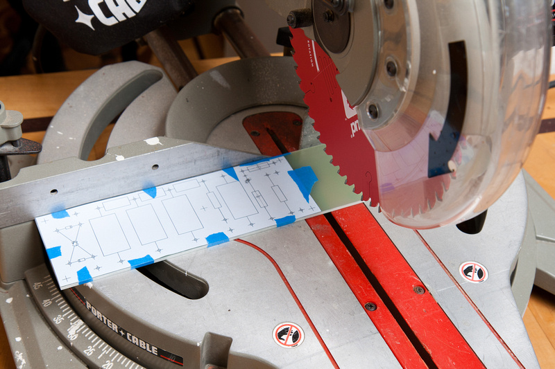
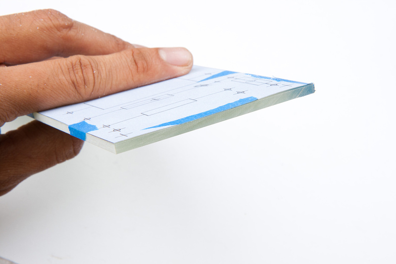
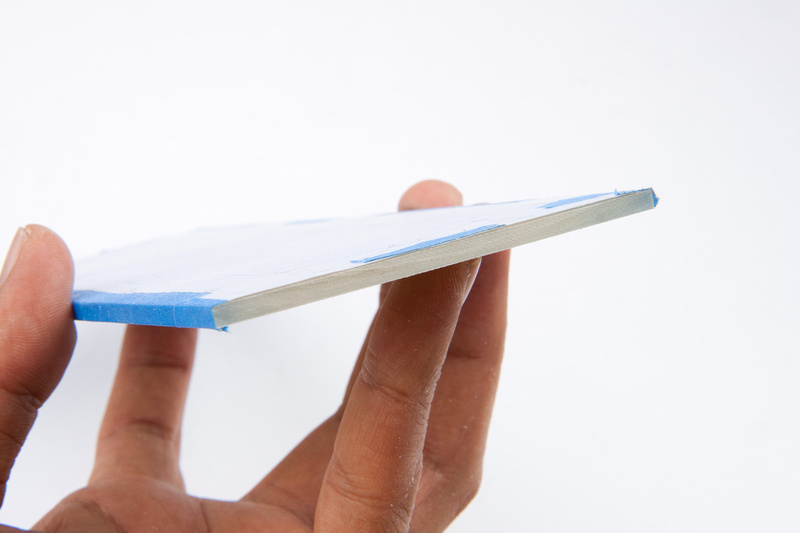
Another trip over to the chop saw renders a clean cut.
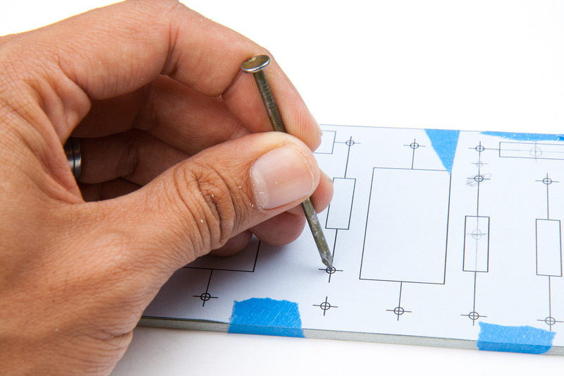
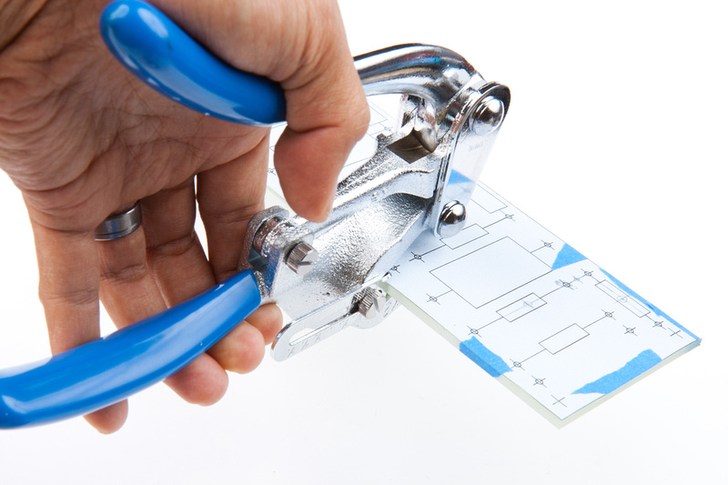
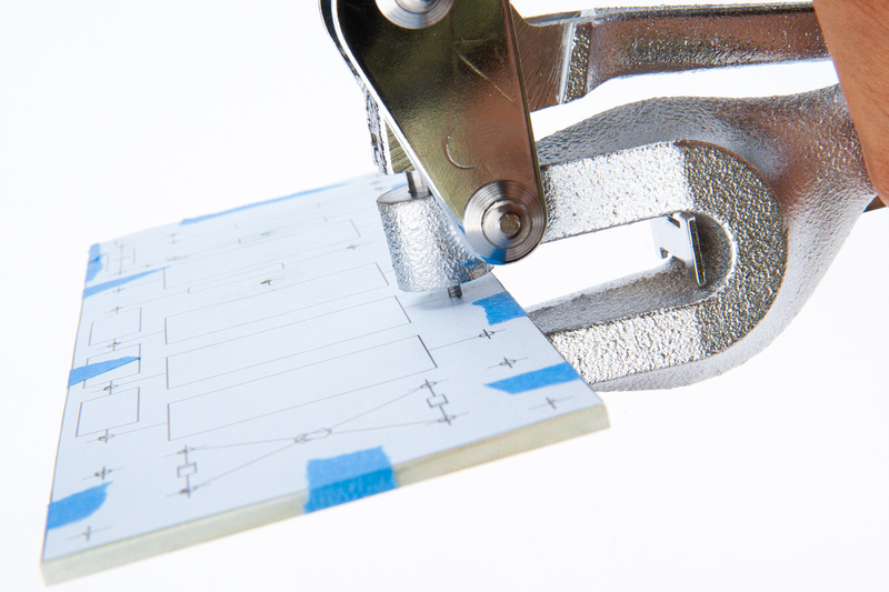
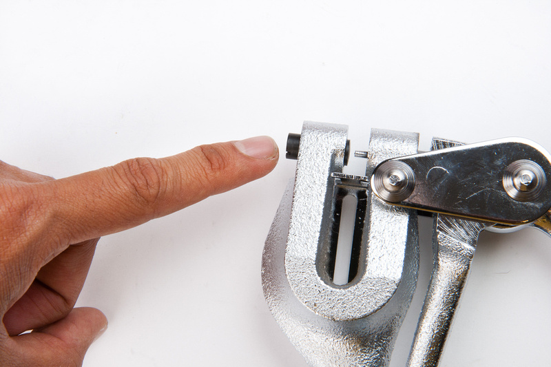
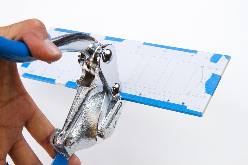
This time around, because the majority of the holes on thsi template are aligned along the long edges, I set the edge distance guide on the Nieko punch tool so I primarily have to visually align the punch from side to side. Also, note I did not feel the need to center-punch the holes this time around as last time, the Neiko punch tool did not track very will with my center-punches anyways. I ended up still aligning everything by eye.
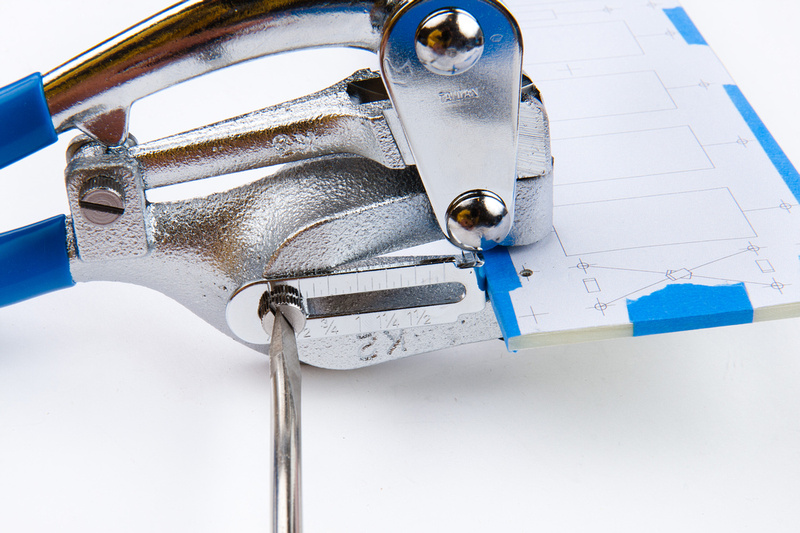
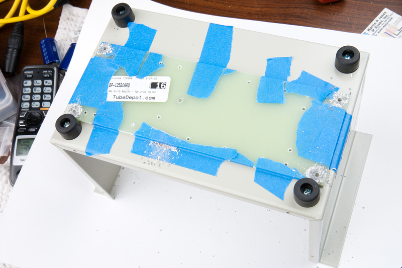
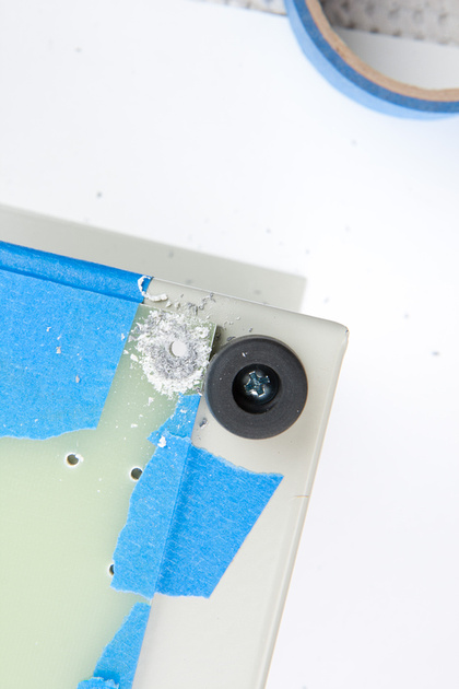
The die portion of the hole-punch tool is not fixed very securely to the frame of the tool. Make sure this die does not drift backwards under use below the level of the chassis. Normally, the material will resist initial punching pressure quite dramatically and the hole will go through with a sharp "POP!". If you feel a bit of mush or softness as the hole starts and the punch pushes through rather smoothly, double check the die height. What happens when it recedes inside the frame is the G10 board will get warped and crushed into the die and make a large-ish white divot on the back side.
Punching the edge holes with guide fixed in position.
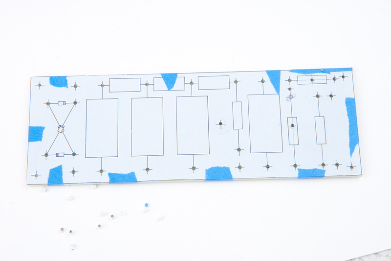
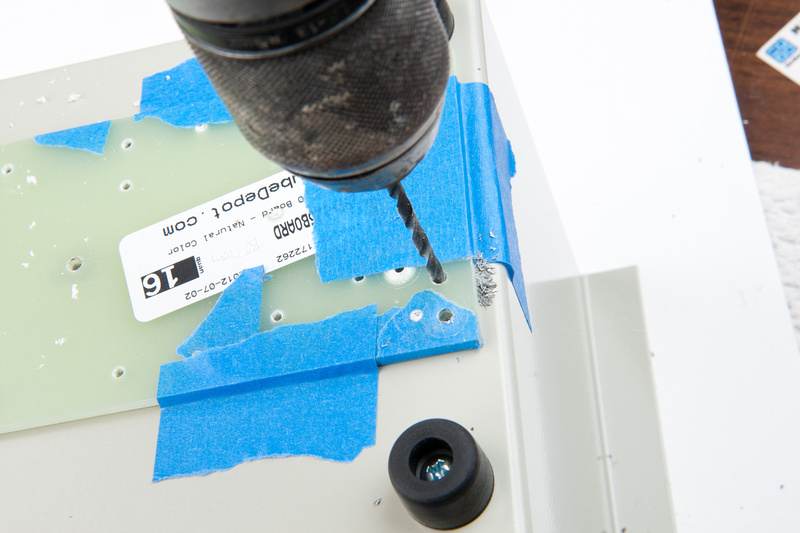
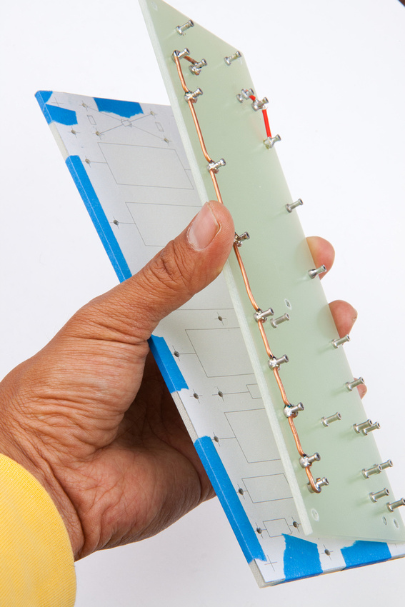
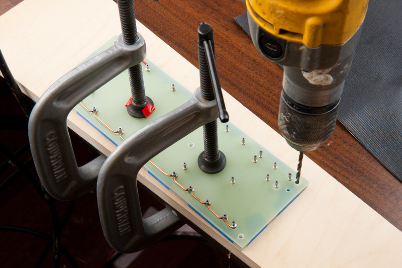
I was able to achieve much better accuracy on my 2nd attempt and had I been this successful on my 1st attempt, I would not have to reference the original (incorrect) board to position my mounting holes as I could simply punch to the template, but because the original board's mounting holes were a little off, and I have already drilled my metal enclosure precisely to fit the old board, I use the old board as a drilling guide to transfer my mounting holes to my new board.
As you can see, the old board is on top and the new board is on the bottom. I drill straight through the old board's original hole into the new board. The position of the new holes are exactly the same as the old board.
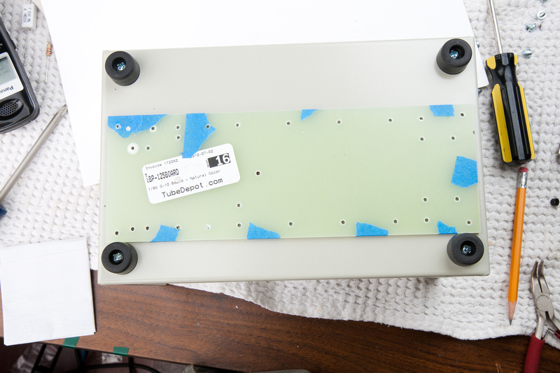
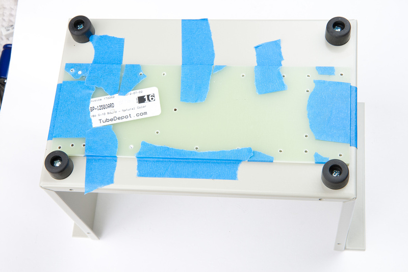
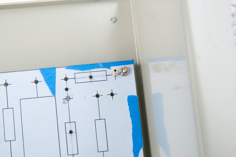
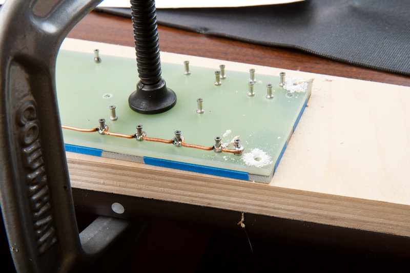
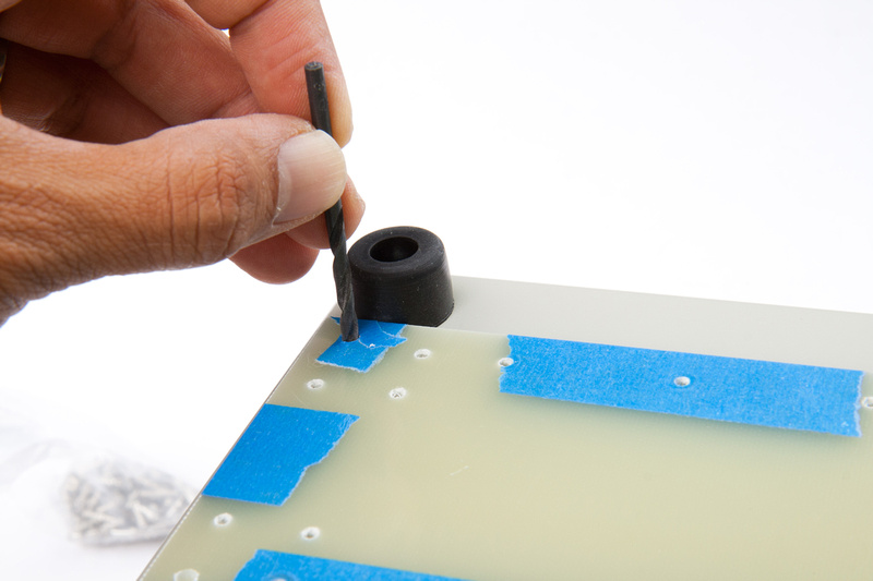
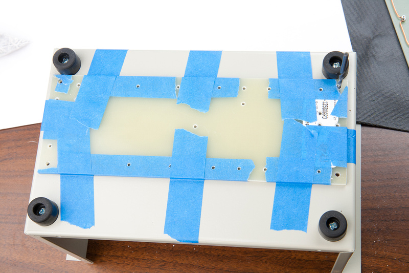
Because one of the original holes now lies directly underneath a capacitor, I had to reposition this one. I will need to drill a new hole in the enclosure. I utilize the drill bit to precisely align my new turret board in position on the bottom of the enclosure.
And tape down securely.
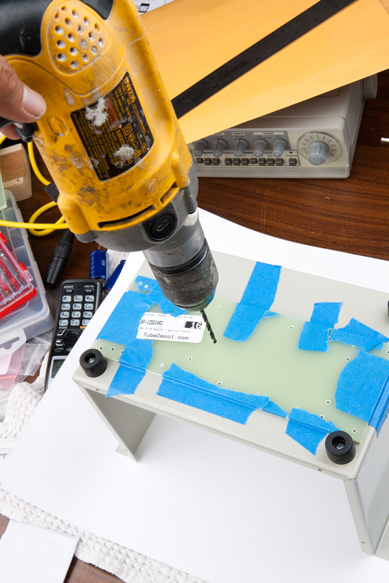
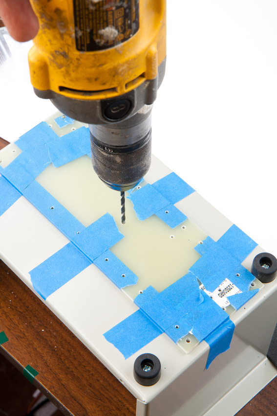
And proceed to drill my newly located center mounting hole into the chassis.
New board is a perfect fit! Humans win.
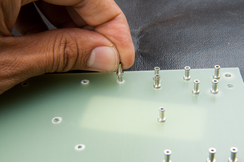
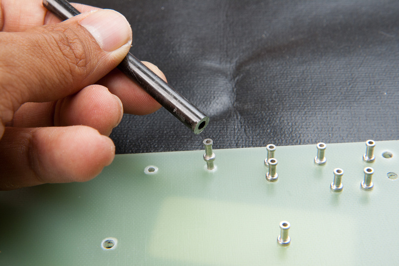
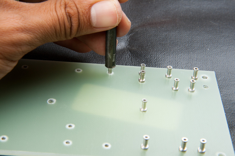
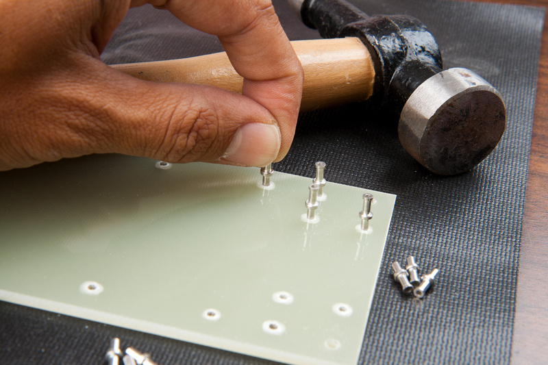
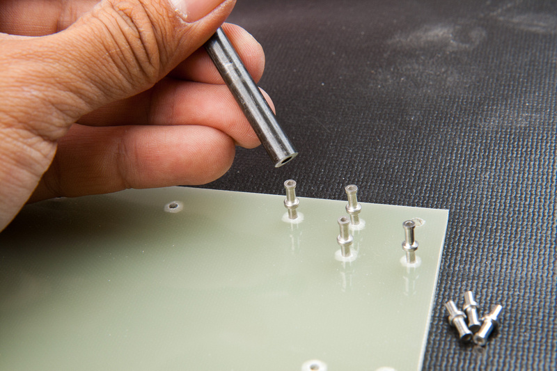
Next, I set my turrets by hand.
And use my turret setting tool purchased from
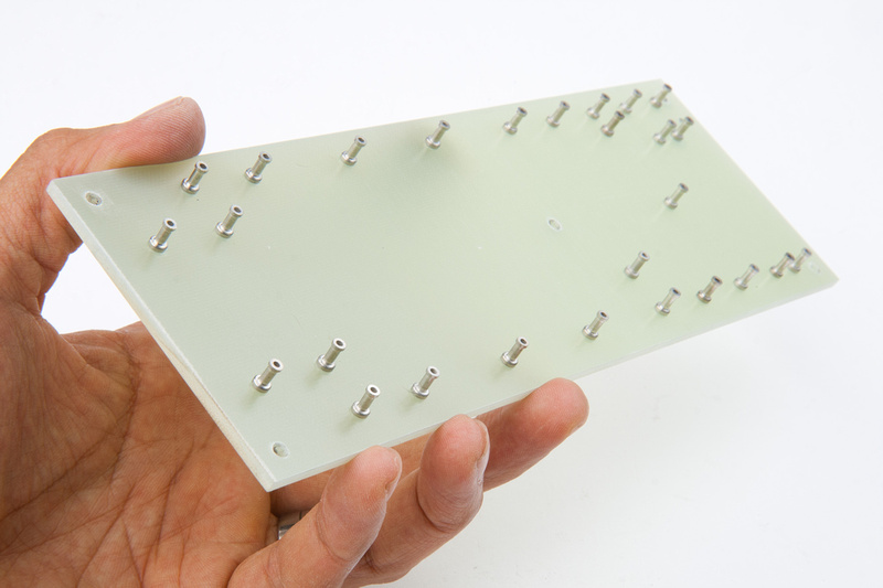
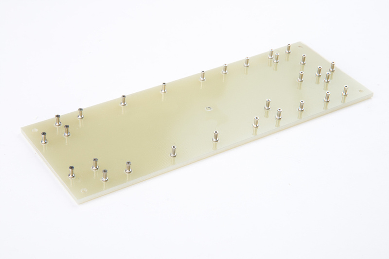
http://www.tubedepot.com/boards.html to drive the turrets until the shoulder is flush with the top surface of the G10 board. Note, I am using my tool kit's supplied soft mat because the turrets protrude below the bottom of the board by design. A mouse pad or other soft surface would also work.
New board is ready to be stuffed. I'm finding this is actually a really fun way to construct a point-to-point board and I glad I'm learning how to do this. I think the build will be very robust and easy to diagnose and service. The fact that it did not come from a kit and you have to lay out and fabricate the board is also very cool. Well, cool until I mess something else up, but time will tell ;D
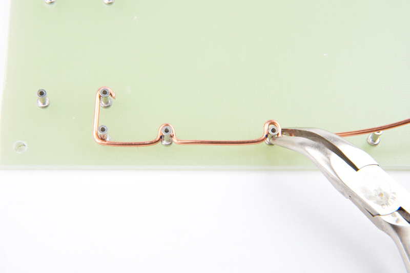
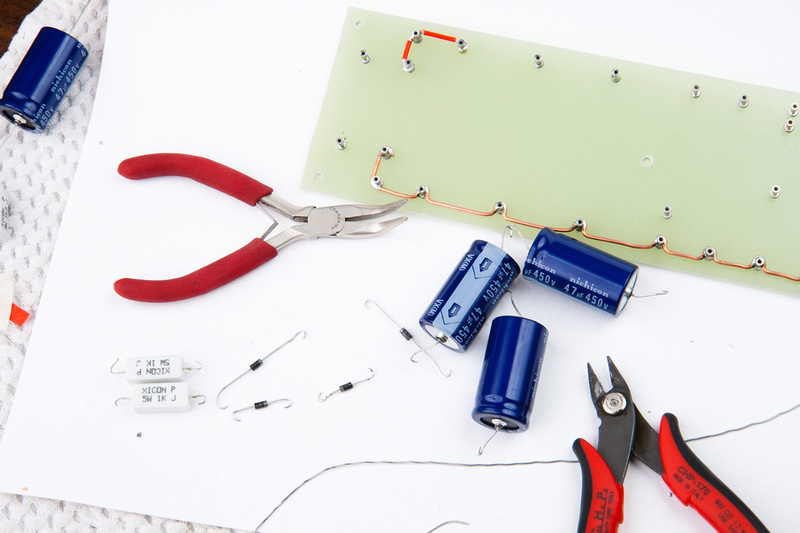
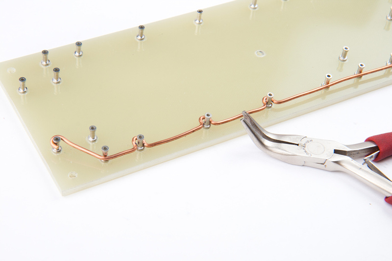
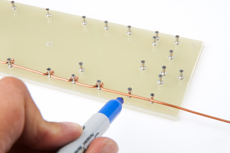
Next, I use a pair of needle nose pliers to bend my 14 gauge ground bus wire. I am using the ground wire from normal household solid core 14 gauge Romex A/C wire that I had left over from building my house.
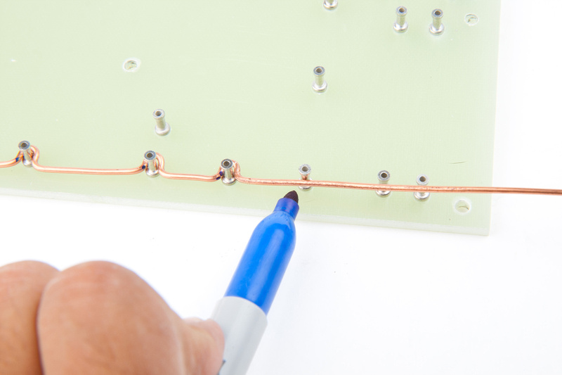
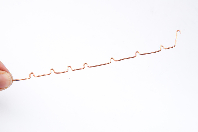
I mark my bend locations as I go and then bend my little "U's" as needed with the small needle nose pliers. I've not seen the ground bus done this way online and there are probably simpler methods that are just as secure, but this is what came to my little twisted mind first and it seems solid so I went with it.
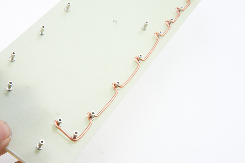
Ground bus wire. . . ready to install.
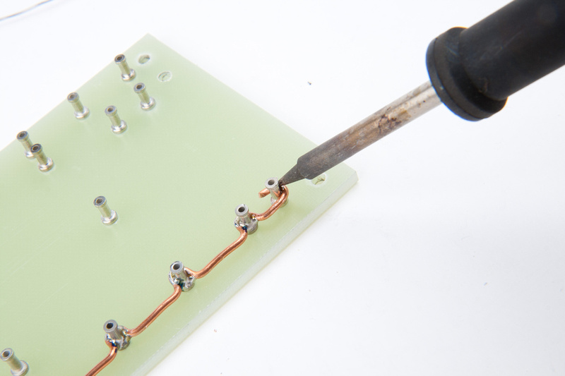
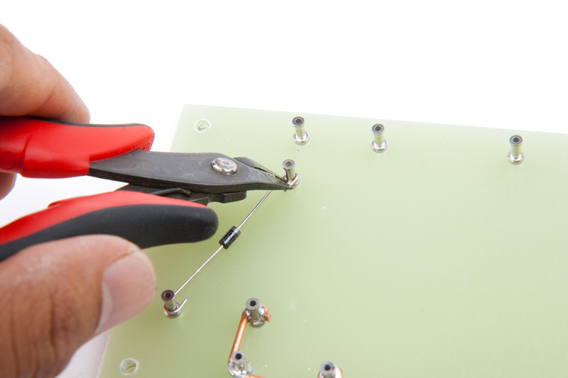
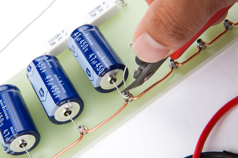
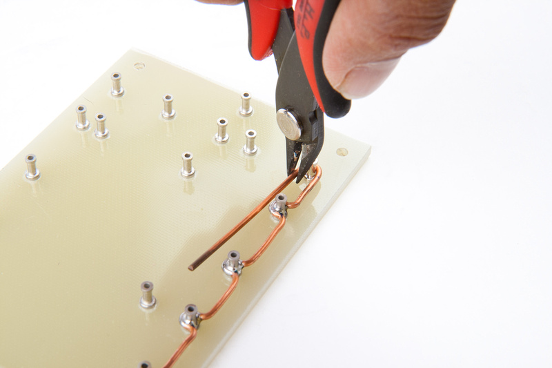
chopping the end of the run as I solder the wire in.
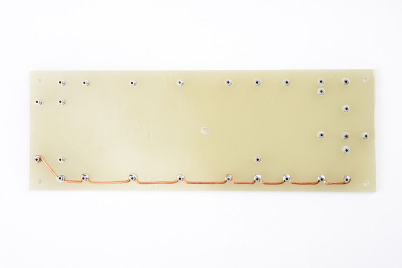
Ground wire is in place.
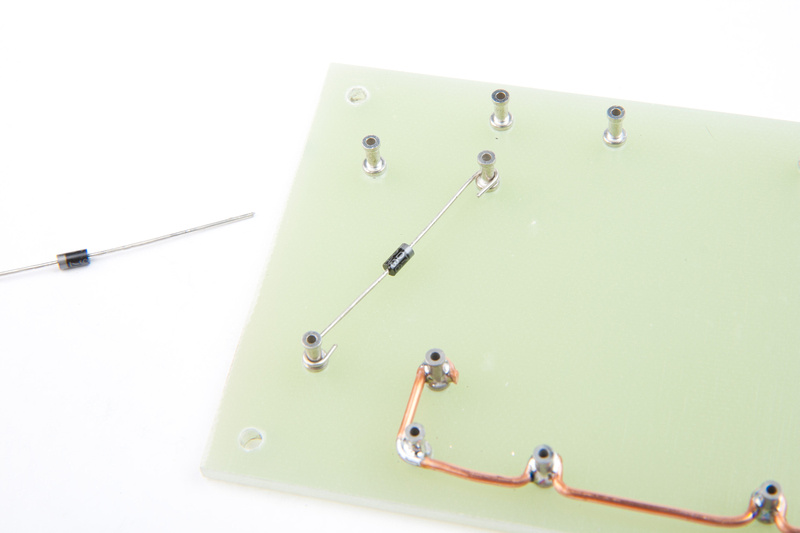
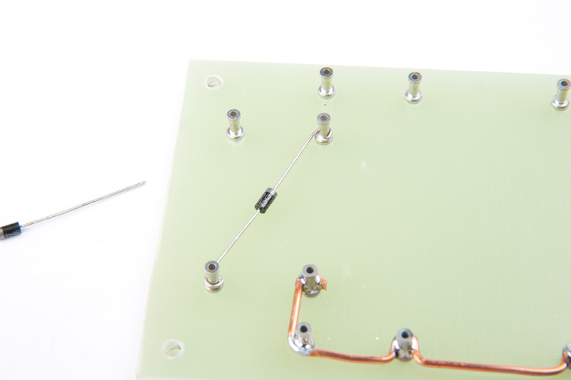
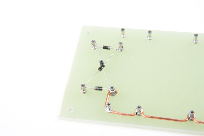
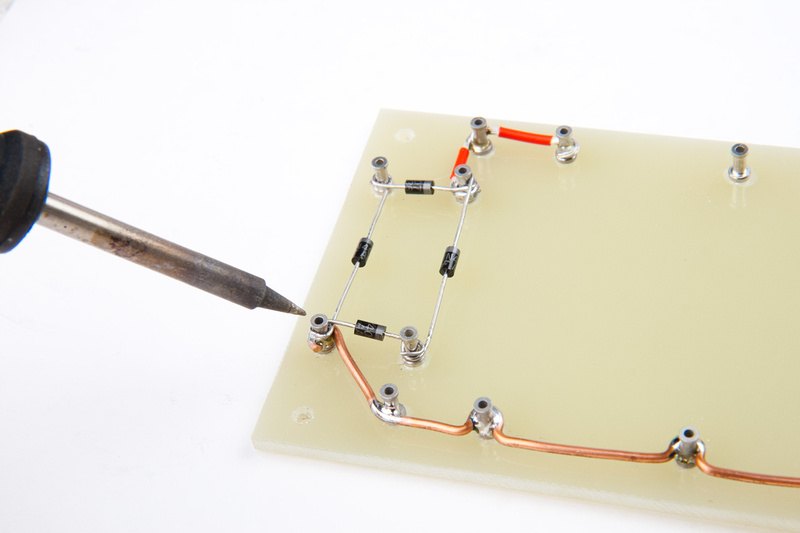
Ok. . . I succumbed to peer pressure. I didn't think that crossing over my diodes would cause so much negativity.

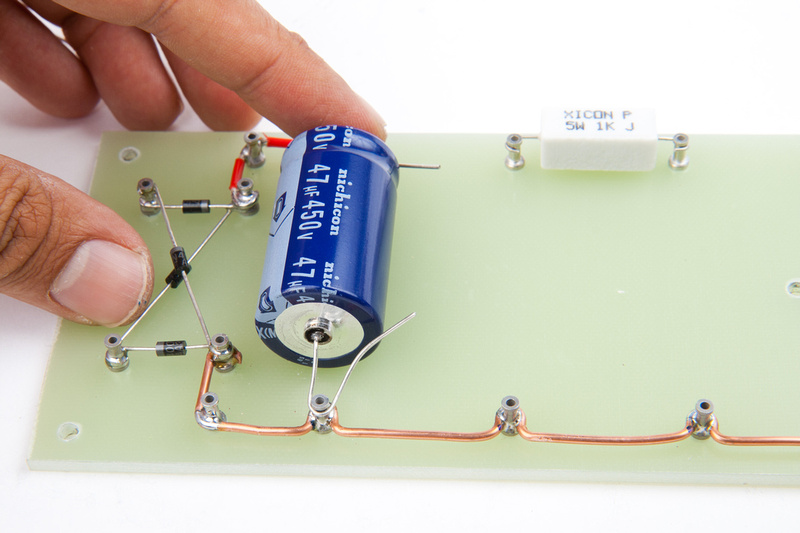
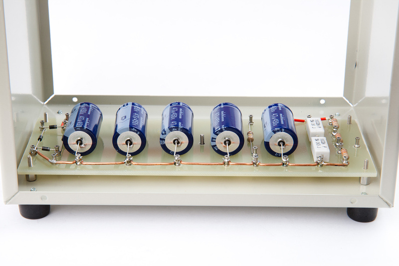
I hope this arrangement makes everyone feel better and helps me not burn my house down. I moved the ground bus wire to the bottom left lug and the A/C from the power toroid will come in on the 2nd lug instead of the 1st as originally planned. No big deal as far as layout goes.
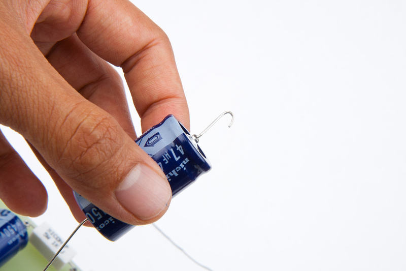
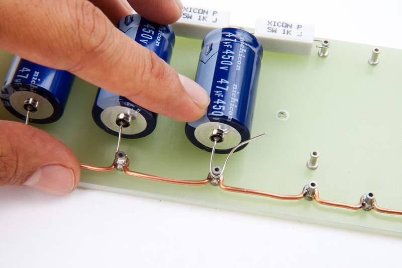
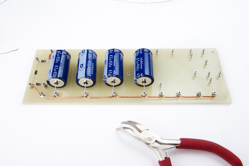
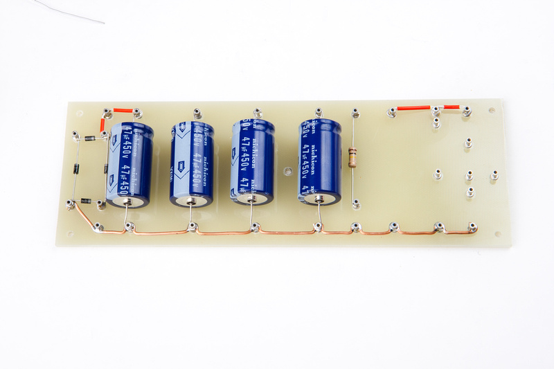
With the main resistors now migrating off of the board, populating is easier and moves along quickly. . . especially because many of the components were removed from my previous board that I messed up, so they were "pre-bent" and ready to go.
On the top-side power rail jumpers, I'm using some 16 gauge silver teflon wire that I purchased a lot of for my original GDIY 51X rack project. I'm sure the wire doesn't have to be that thick, but it doesn't hurt either.
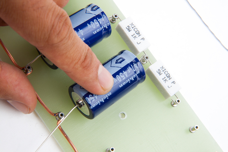
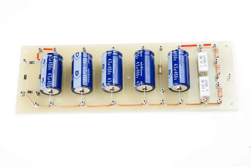
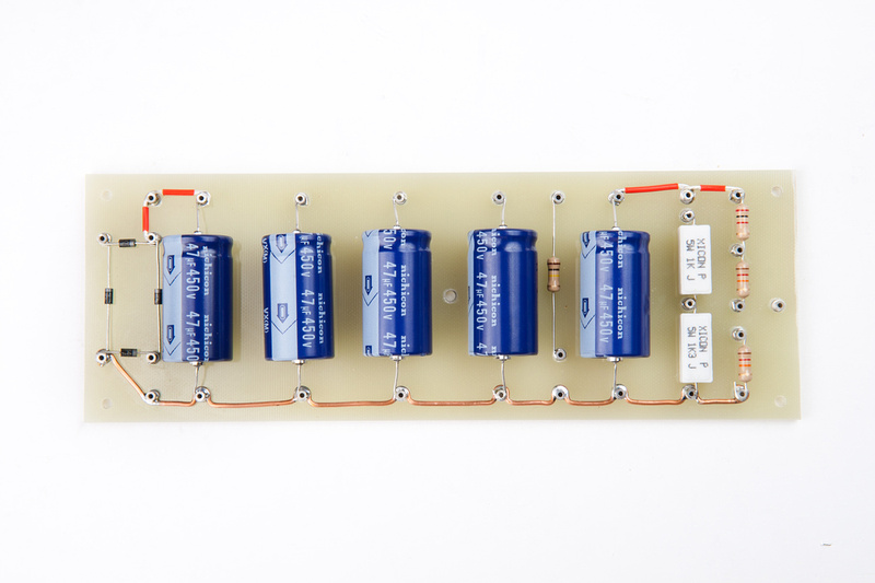
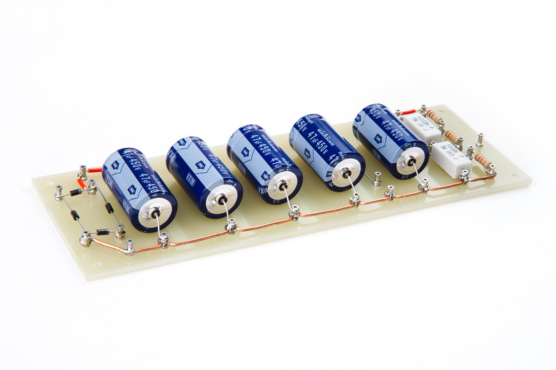
And, the new turret board is populated. Humans win!
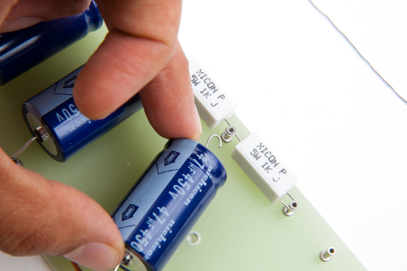
Note I used the originally planned 5W test resistors (1K + 1.3K is series) mounted on the PCB. My thought is I will not run this board in test mode for extended periods of time so I can live with the extra heat generated on the PCB during calibration process, but for the most part, the board will run on the chassis-mounted main resistors that I am waiting for from Mouser.
The diodes could have been aligned better, but these were more difficult too place after removal from the old board. If I build another one, I can clean those up, but nothing wrong with this. It is mechanically/functionally solid.
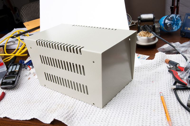
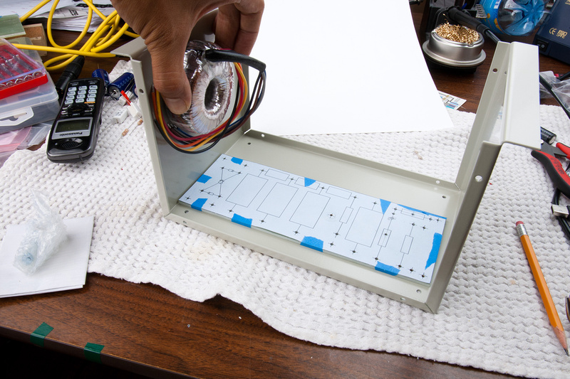
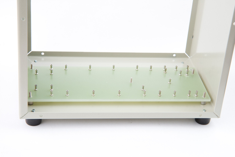
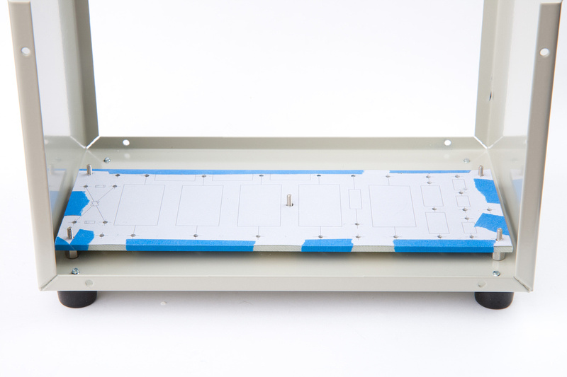
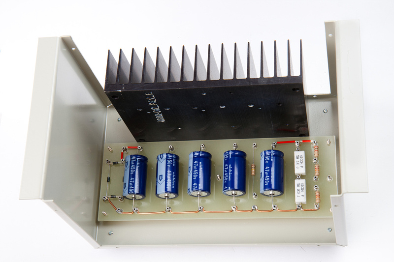
Upon temporary fitting, everything looks like it will work.
So, after more than a few initial setbacks, I am back on track and making forward progress! As usual, if anybody spots a critical or not-so critical error, please let me know so i can attempt to fix it before I burn my house down.
 . I'm contemplating building on the t.bone sct700 as the kit seems to have been designed to fit the mounting holes exactly. I'm looking forward to getting back into this project when I receive funds from USPS.


![Soldering Iron Kit, 120W LED Digital Advanced Solder Iron Soldering Gun kit, 110V Welding Tools, Smart Temperature Control [356℉-932℉], Extra 5pcs Tips, Auto Sleep, Temp Calibration, Orange](https://m.media-amazon.com/images/I/51sFKu9SdeL._SL500_.jpg)


