chunger
Well-known member
OK. . . a lot more hacking last night. I was just thinking Zayance has a nice power supply PCB and Dany at http://www.collectivecases.com has a pre-drilled case that probably would have been a good idea, silly me decided I wanted to "learn something" and here we are 
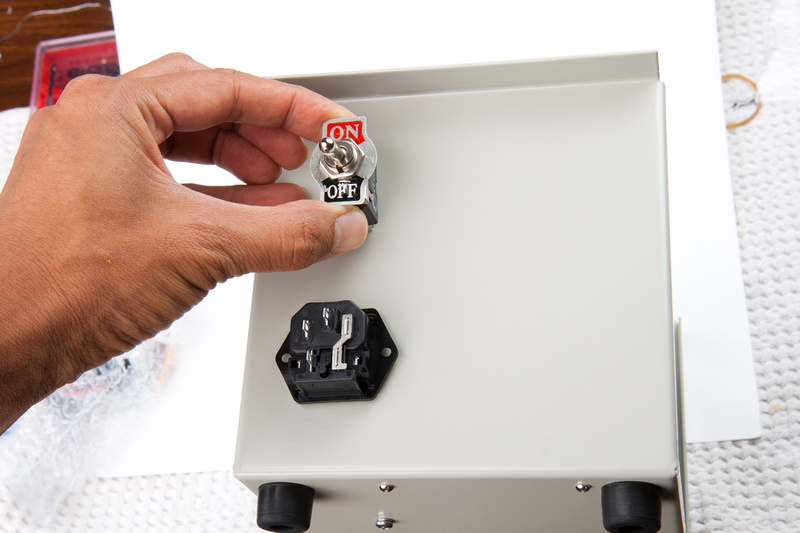
ok. . . onward. Next I go for the back side of the PSU case with the power switch and IEC power jack.
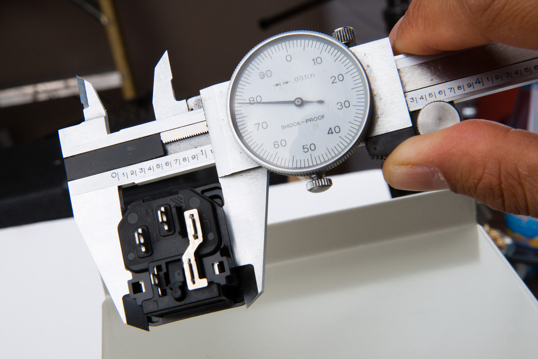
I get an accurate measurement of the hole I need.
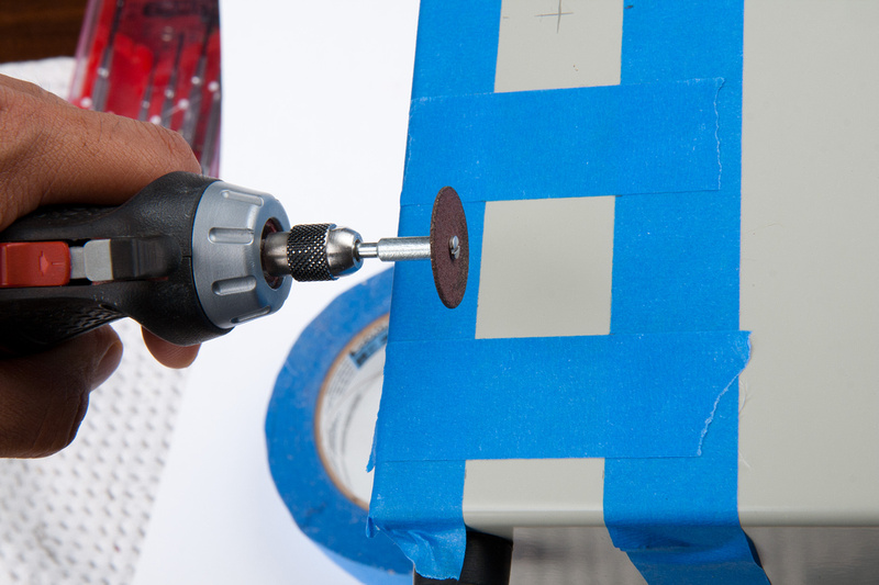
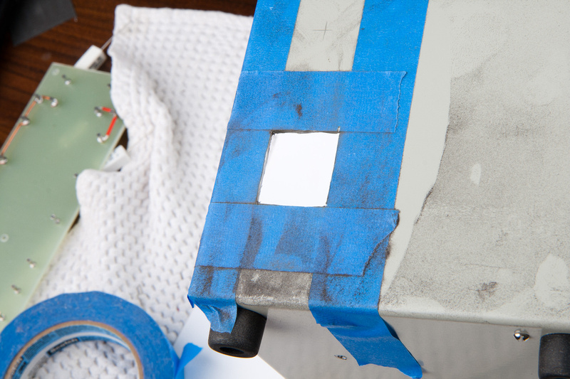
Use painter's tape to mark the location and use metal cut-off blades on a rotary tool to cut my square hole.
Fits.
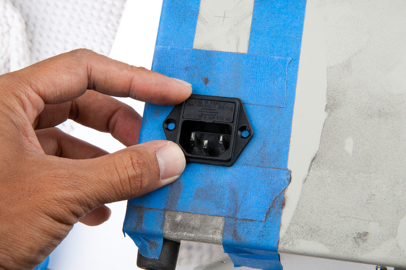
I go ahead and use the part to guide the drill for screw holes.
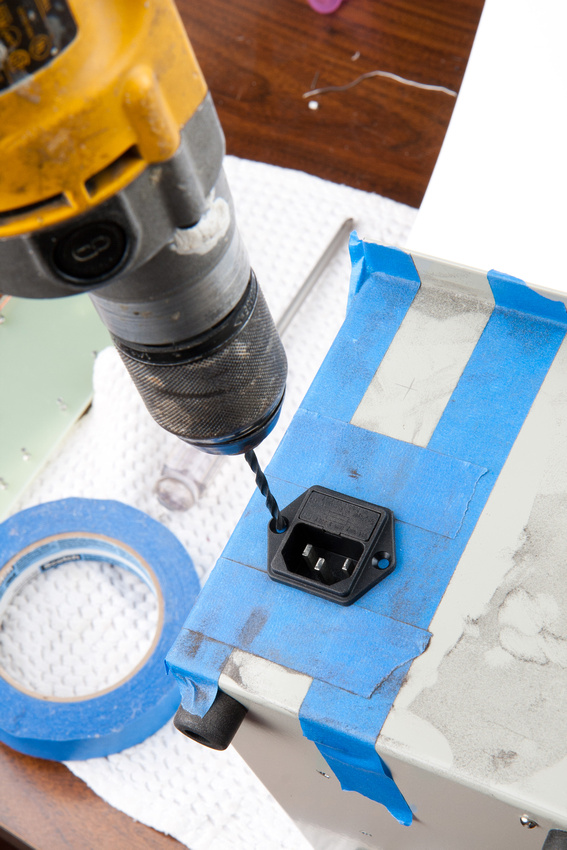
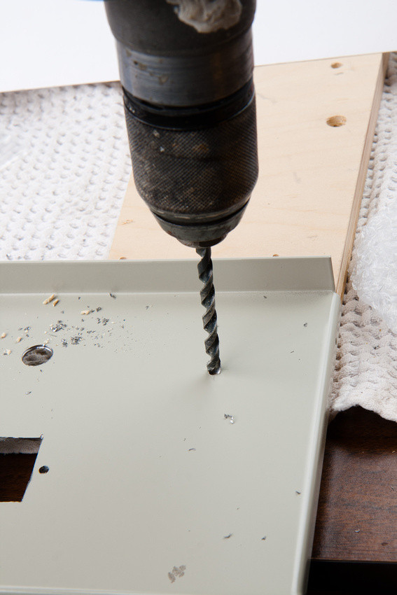
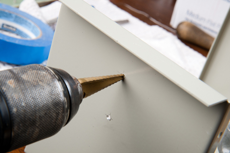
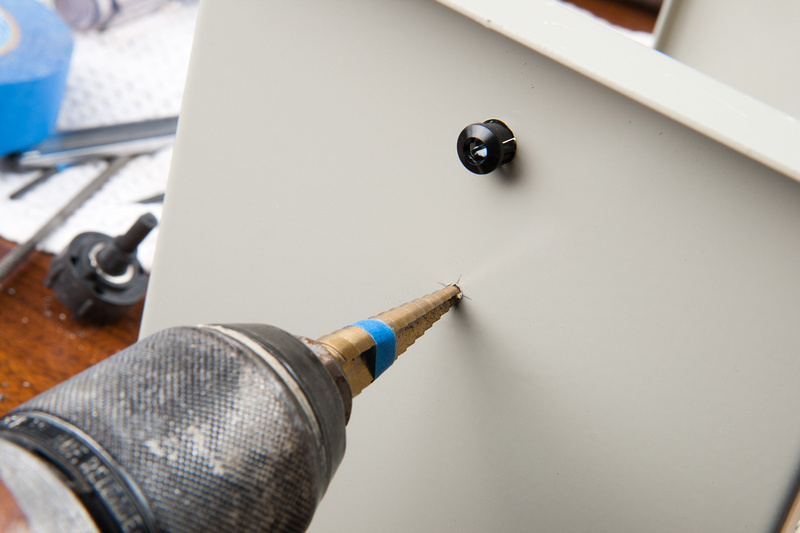
Next, I center punch the hole for the power switch.
small hole to start.
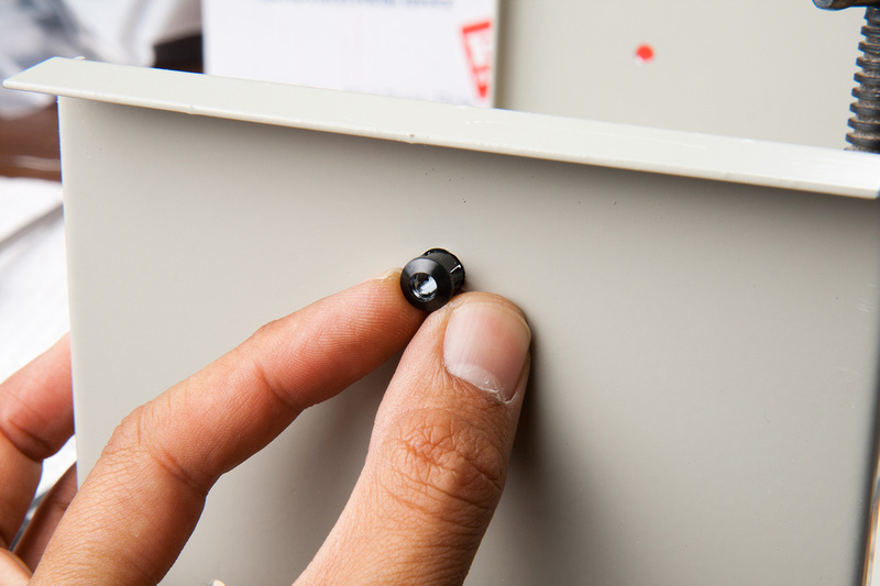
and follow with a Nieko unibit purchased on amazon.com . This tends to walk a bit less than a drill bit for the bigger holes.
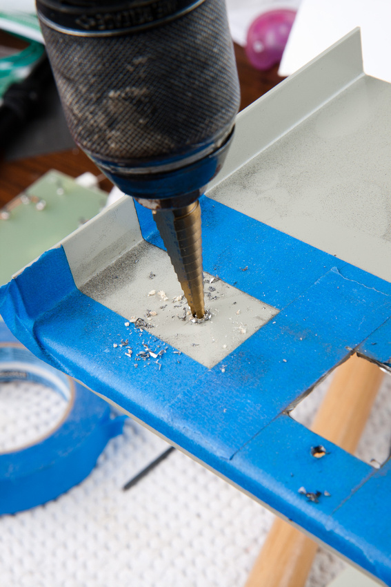
smooth! I like this bit a lot. Cuts the mild steel with ease.
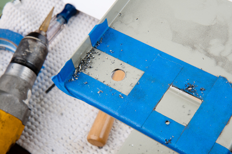
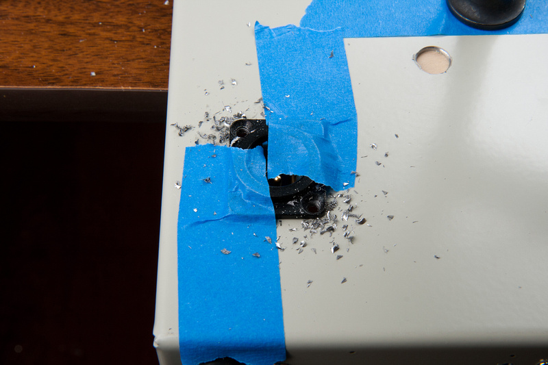
Next, I locate my toroid's final position.
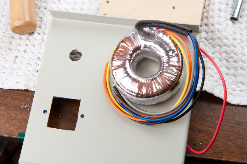
And mark center with a pencil. There is a lot of room to spare here, so I do not need to be very precise.
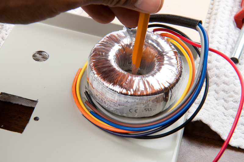
and drill my mount hole for the toroid bolt.
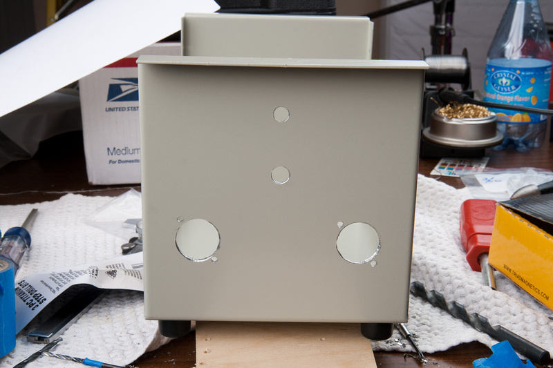
back side is drilled.
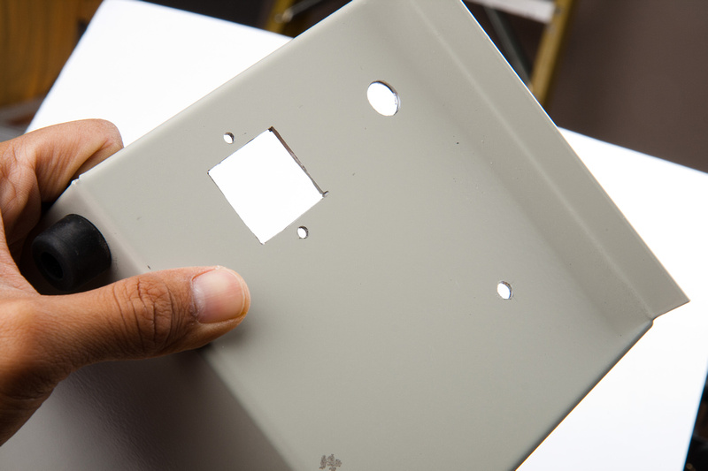
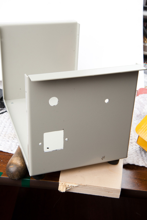
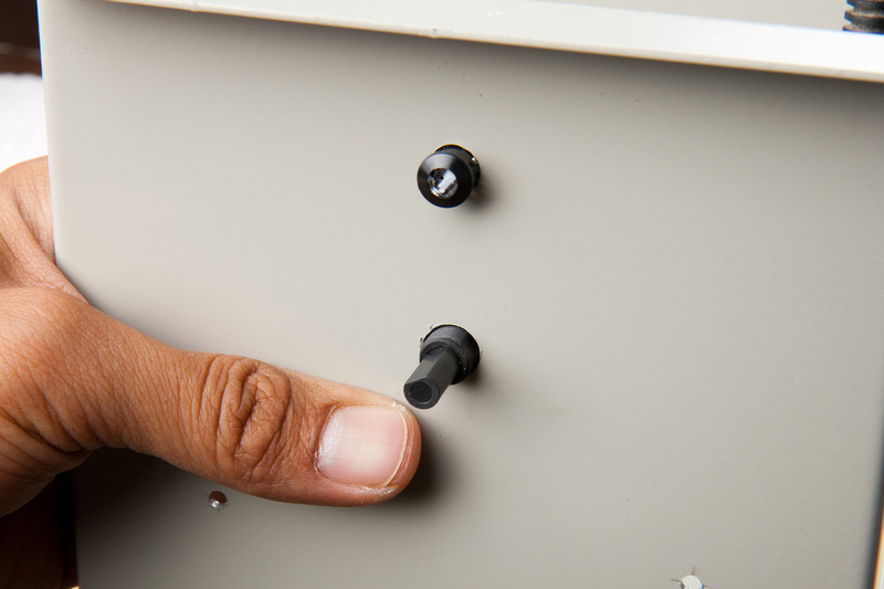
quick test fit to see how things look in place and verify clearances.
. . . and it looks like we are ok.
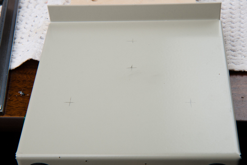
Next, I move to the front side and position my components. LED bezel, pattern rotary switch, input 7 pin XLR, and output 3 pin XLR.
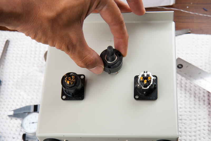
component locations marked.
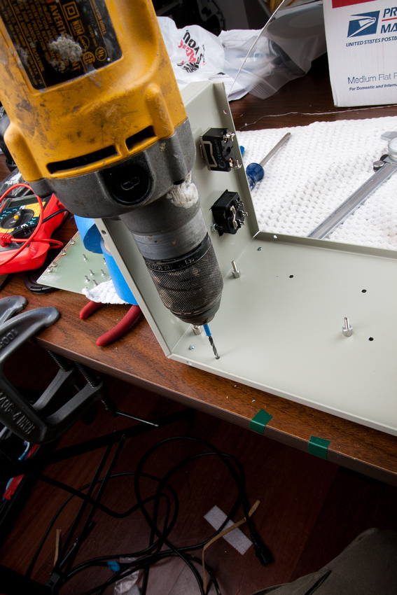
Next, I center punch and drill with a small bit to start,
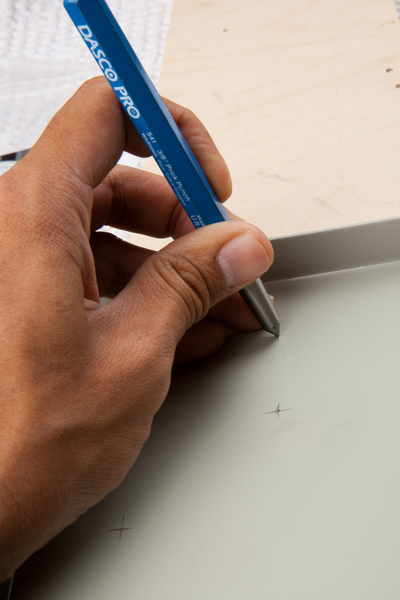
. . . and follow with the unibit to bring the holes to final diameter.
LED bezel fits nicely.
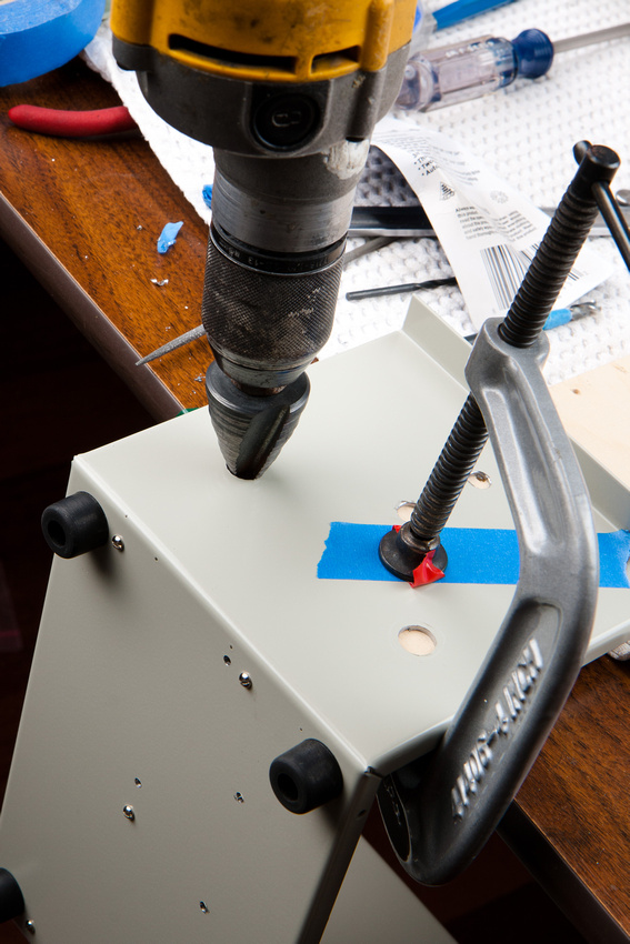
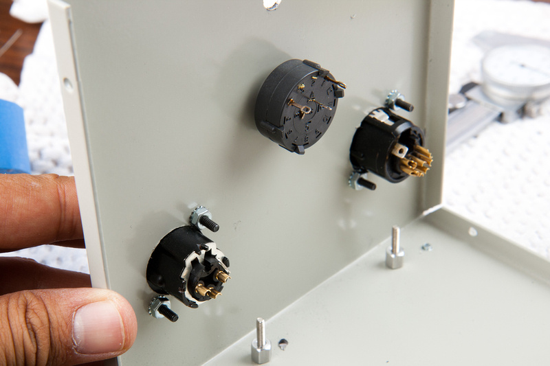
Next, the pattern switch.
For the XLR D-type Neutrik connectors, I will have to use a large unibit to bring the holes up to diameter. Note, this large diameter bit can buck something fierce if it catches and fling your work piece across the room, bend the case, and/or injure your wrist particularly if you are using a high torque drill like I am using here, so please clamp the piece securely and make sure you are in a position with lots of mechanical advantage and stability when drilling these holes.
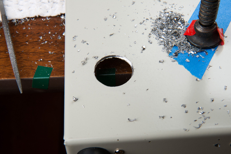
Bam!
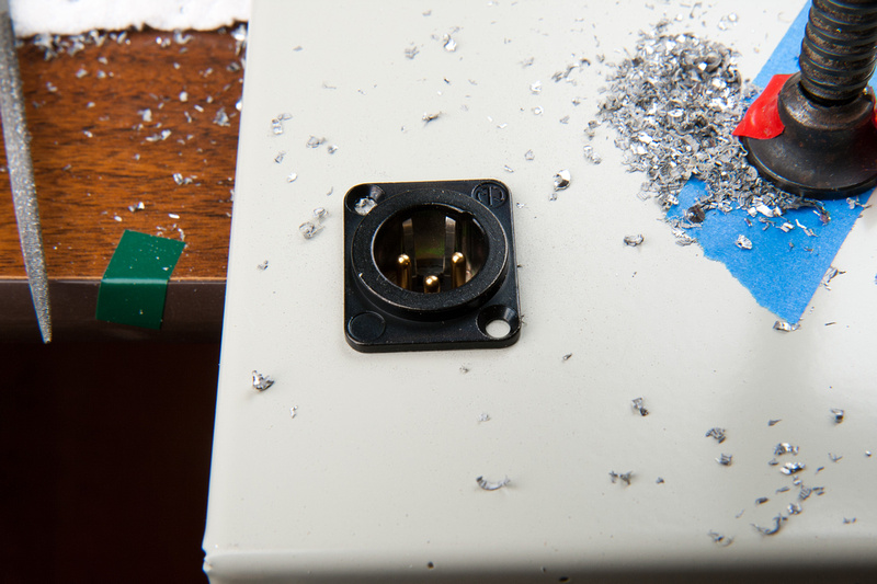
Repeat for the other side.
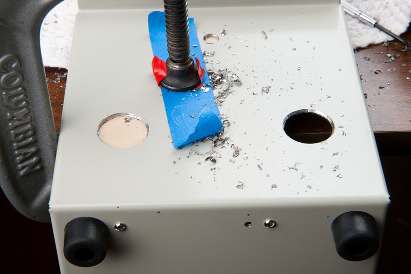
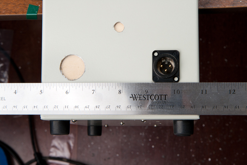
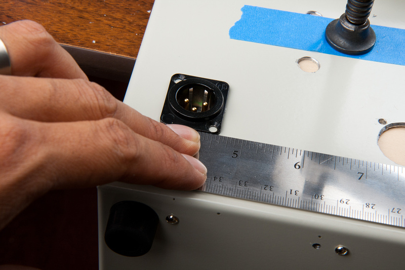
I use a ruler to position align the XLR jack with the enclosure.
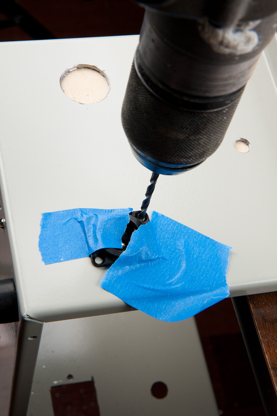
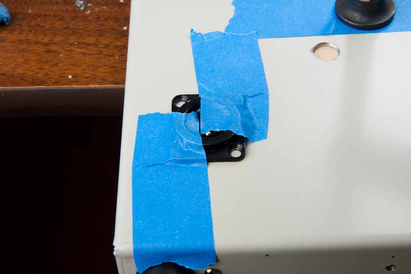
tape it down with painter's tape and use the jack as a drill guide.
and repeat for the other side.
Perfect!
and front side holes are bored.
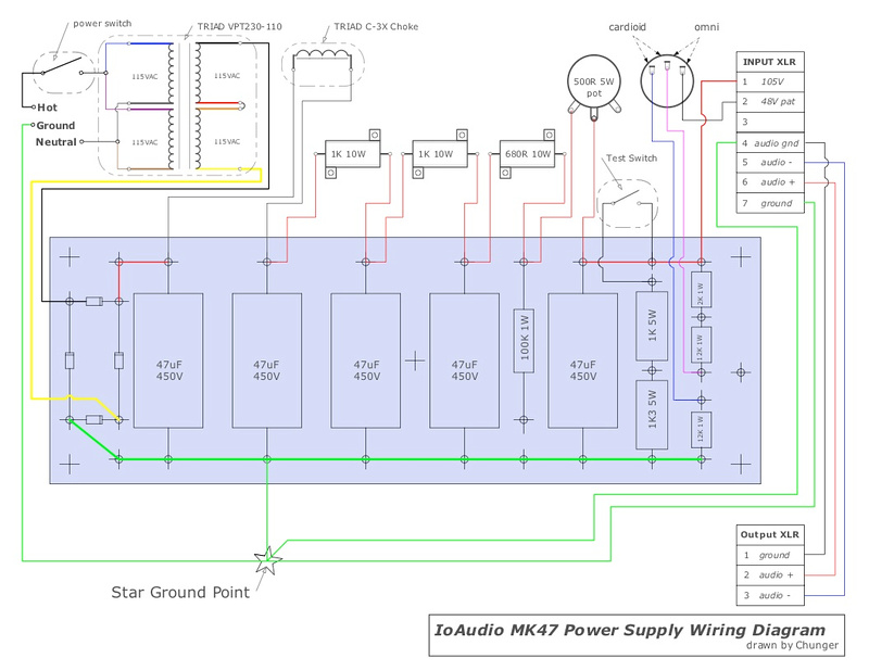
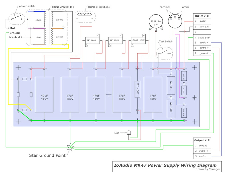
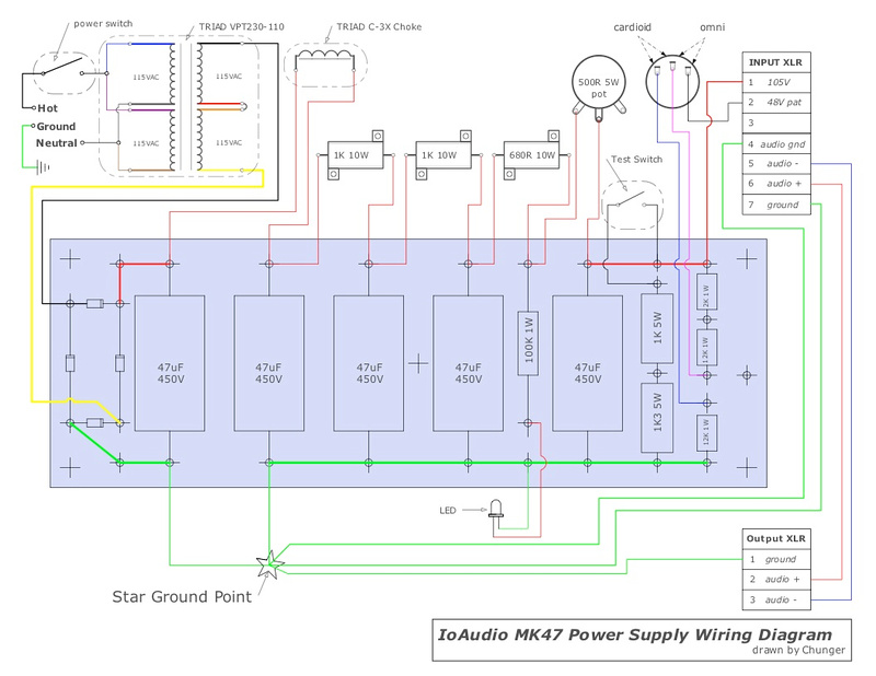
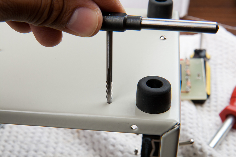
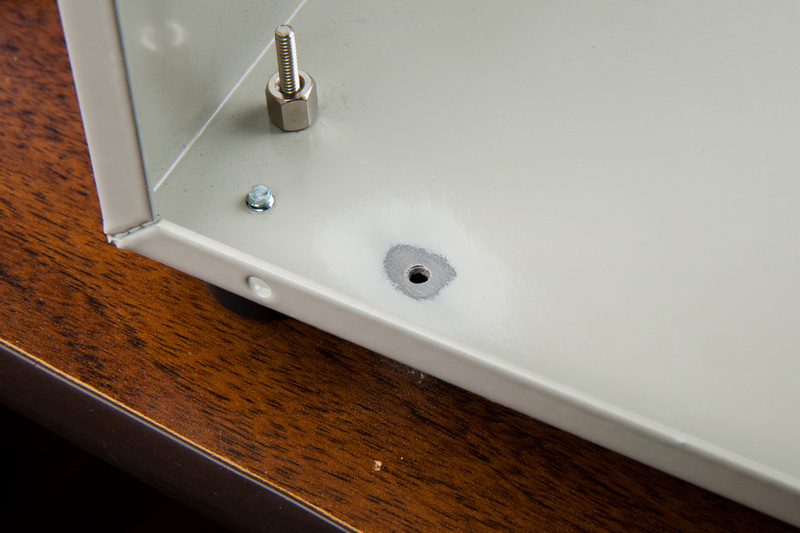
One last important hole in the enclosure . My star ground point. I choose to ground near the 1st capacitor after the choke because I read somewhere on the internet that that is a good position for my primary star ground. I'm using a #36 bit here and will tap for 6-32.
I grab some 220 sandpaper and wrap it around a pencil eraser.
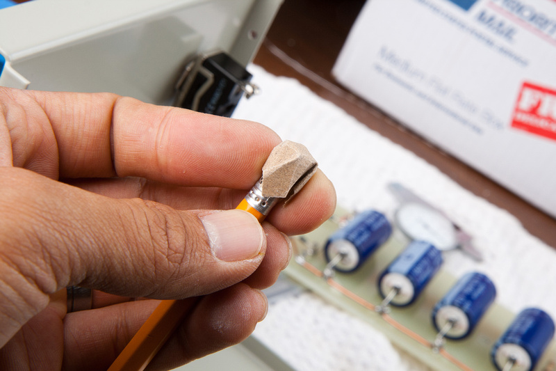
and "erase" some of the powder coating surrounding the ground point so my tab will make solid contact with the enclosure.
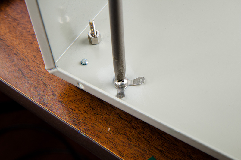
and screw my solder tab to the star ground point.
more flat head 4-40 screws and locking nuts secure my Neutrik input/output jacks.
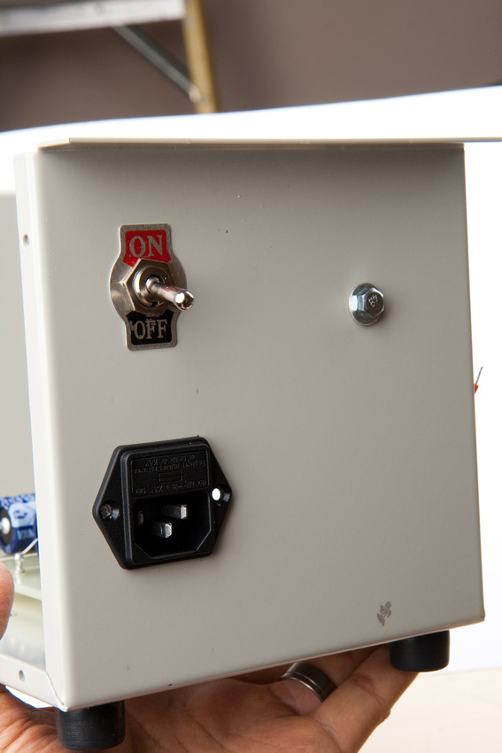
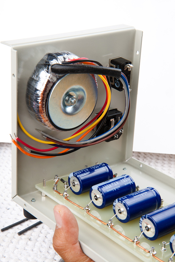
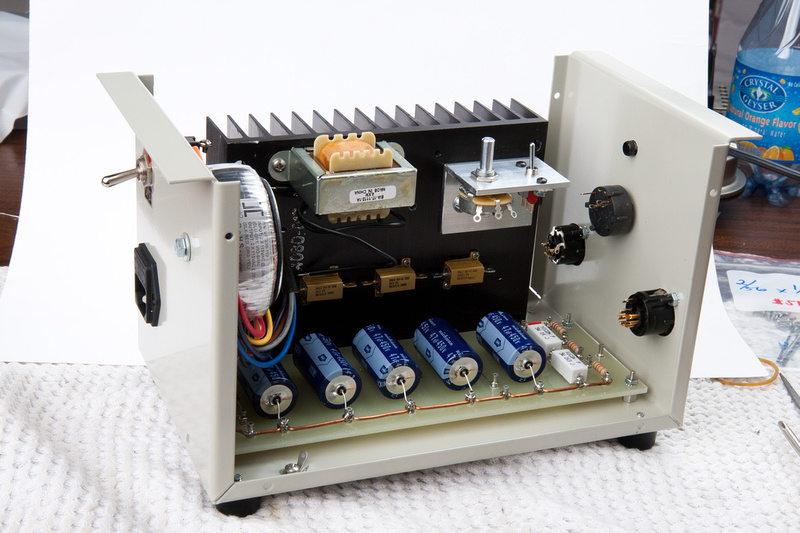
back-side power components in position.
I re-install the turret board.
And the heat sink assembly. Now, all components are in position and I just need to wire the connections.
Humans Win!
ok. . . onward. Next I go for the back side of the PSU case with the power switch and IEC power jack.
I get an accurate measurement of the hole I need.
Use painter's tape to mark the location and use metal cut-off blades on a rotary tool to cut my square hole.
Fits.
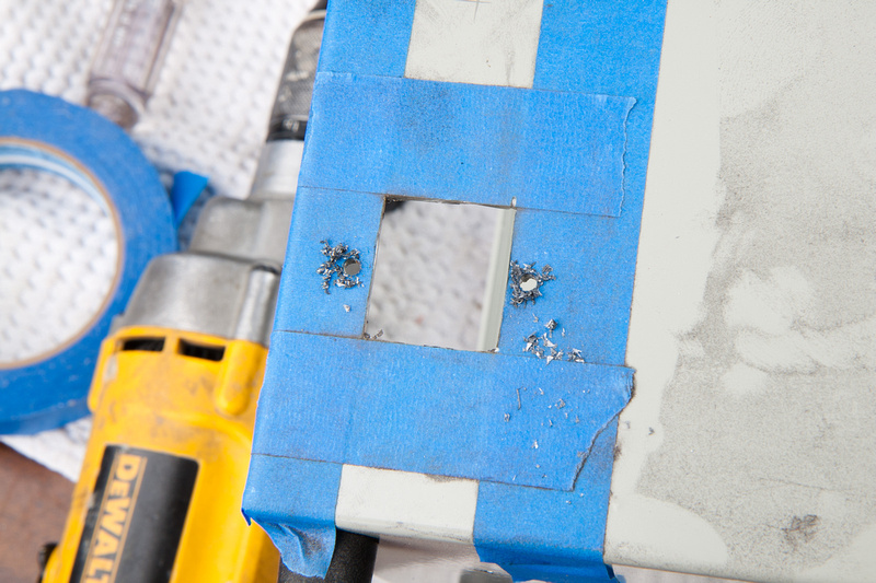
I go ahead and use the part to guide the drill for screw holes.
Next, I center punch the hole for the power switch.
small hole to start.
and follow with a Nieko unibit purchased on amazon.com . This tends to walk a bit less than a drill bit for the bigger holes.
smooth! I like this bit a lot. Cuts the mild steel with ease.
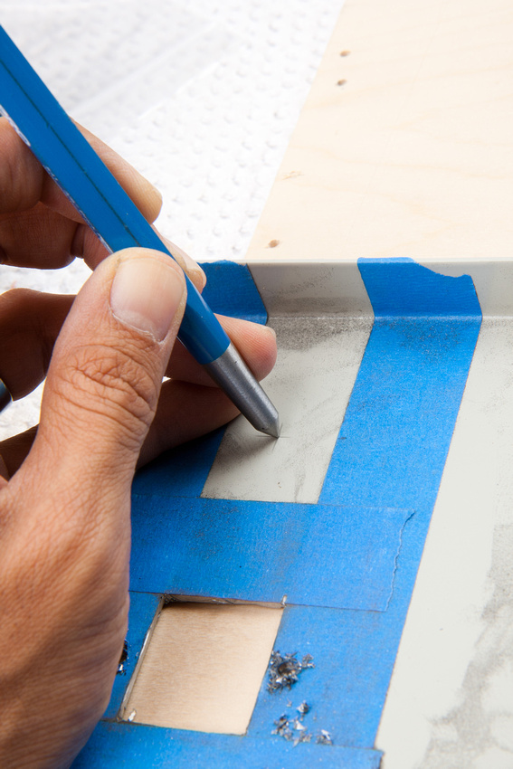
Next, I locate my toroid's final position.
And mark center with a pencil. There is a lot of room to spare here, so I do not need to be very precise.
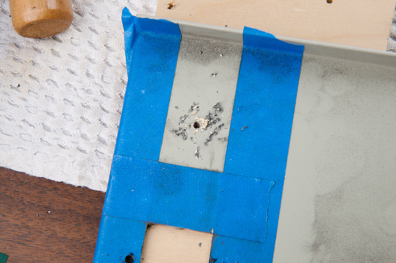
and drill my mount hole for the toroid bolt.
back side is drilled.
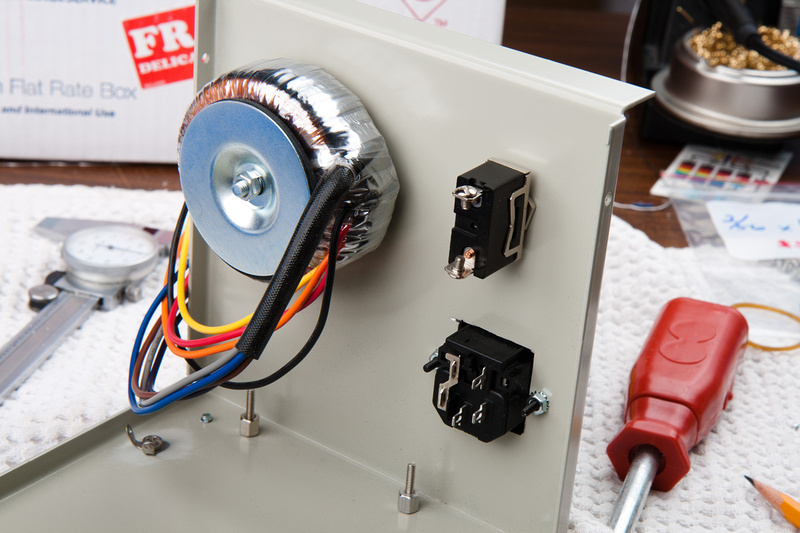
quick test fit to see how things look in place and verify clearances.
. . . and it looks like we are ok.
Next, I move to the front side and position my components. LED bezel, pattern rotary switch, input 7 pin XLR, and output 3 pin XLR.
component locations marked.
Next, I center punch and drill with a small bit to start,
. . . and follow with the unibit to bring the holes to final diameter.
LED bezel fits nicely.
Next, the pattern switch.
For the XLR D-type Neutrik connectors, I will have to use a large unibit to bring the holes up to diameter. Note, this large diameter bit can buck something fierce if it catches and fling your work piece across the room, bend the case, and/or injure your wrist particularly if you are using a high torque drill like I am using here, so please clamp the piece securely and make sure you are in a position with lots of mechanical advantage and stability when drilling these holes.
Bam!
Repeat for the other side.
I use a ruler to position align the XLR jack with the enclosure.
tape it down with painter's tape and use the jack as a drill guide.
and repeat for the other side.
Perfect!
and front side holes are bored.
One last important hole in the enclosure . My star ground point. I choose to ground near the 1st capacitor after the choke because I read somewhere on the internet that that is a good position for my primary star ground. I'm using a #36 bit here and will tap for 6-32.
I grab some 220 sandpaper and wrap it around a pencil eraser.
and "erase" some of the powder coating surrounding the ground point so my tab will make solid contact with the enclosure.
and screw my solder tab to the star ground point.
more flat head 4-40 screws and locking nuts secure my Neutrik input/output jacks.
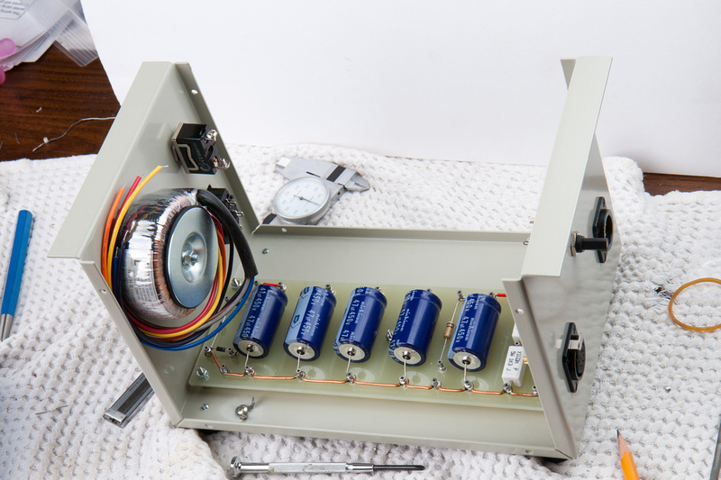
back-side power components in position.
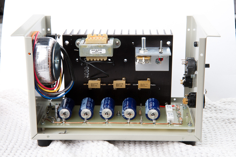
I re-install the turret board.
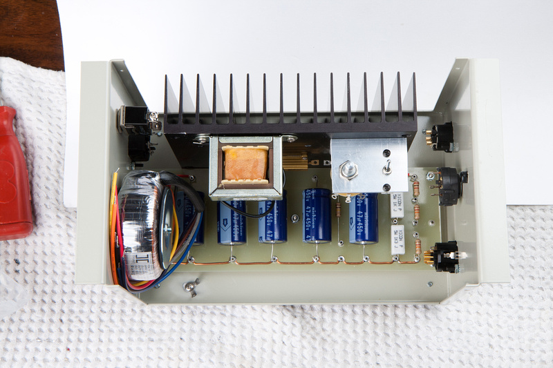
And the heat sink assembly. Now, all components are in position and I just need to wire the connections.
Humans Win!


![Soldering Iron Kit, 120W LED Digital Advanced Solder Iron Soldering Gun kit, 110V Welding Tools, Smart Temperature Control [356℉-932℉], Extra 5pcs Tips, Auto Sleep, Temp Calibration, Orange](https://m.media-amazon.com/images/I/51sFKu9SdeL._SL500_.jpg)