newbie builds ioaudio MK47 microphone

GroupDIY Audio Forum

Help Support GroupDIY Audio Forum:

This site may earn a commission from merchant affiliate links, including eBay, Amazon, and others.
Wow, if everyone started posting builds with as nice and thorough pictures as this one is, I think I would be content browsing them all day and living vicariously through them! Looks great!
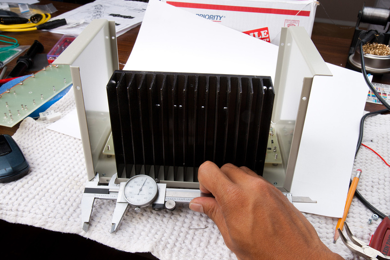
 
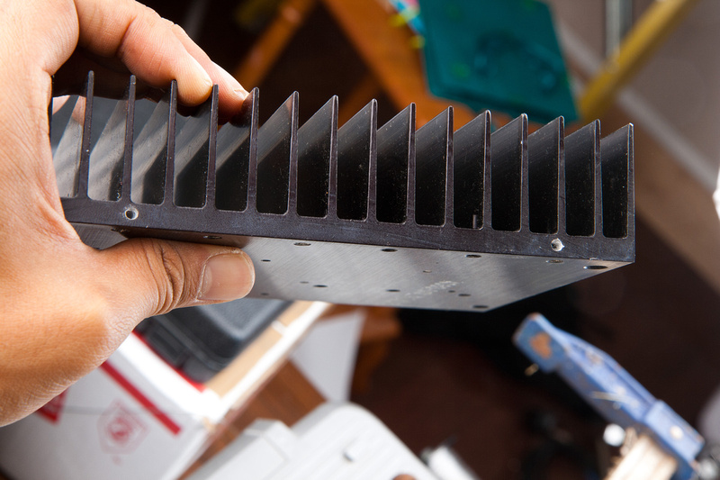
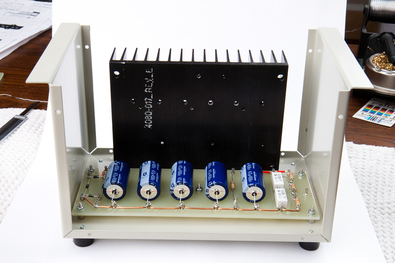
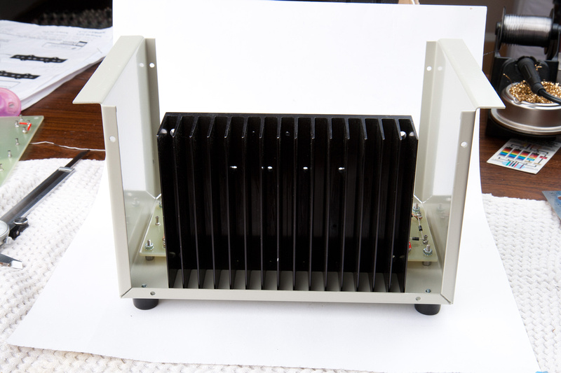
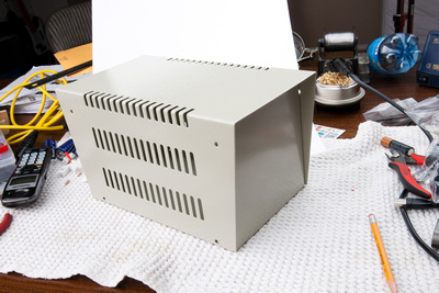
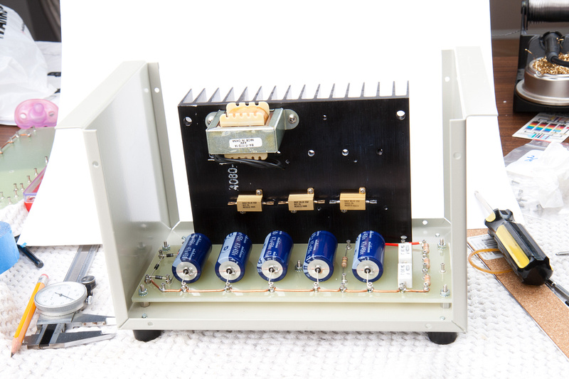
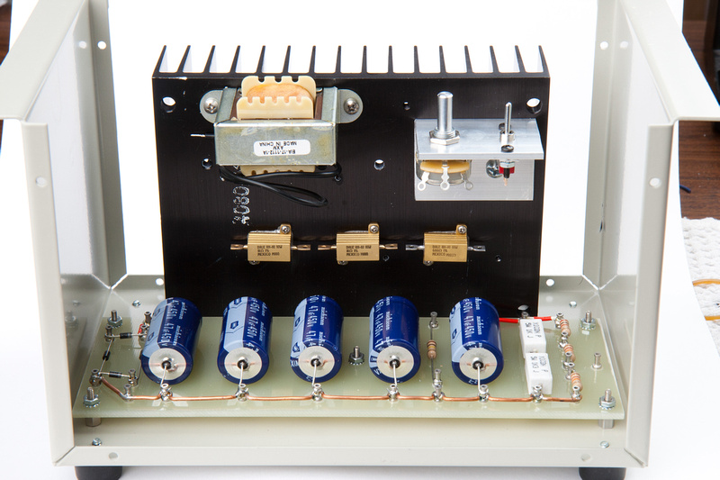
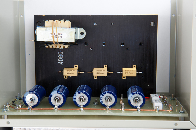
OK. . . the heatsink looked too cool to not do.  It utilizes the space I have inside of this tall enclosure purposefully and allows me to mount a lot components on it.  Plus, the fins line up amazingly well with the vent holes on the enclosure, and obviously it will help dissipate the heat generated from the hot resistors extending the service life of this power supply.

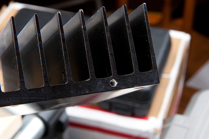
I figured the cleanest way to mount this heat sink is to drill a few holes directly through the bottom of the enclosure and into the core section of the heat sink which is only .265 inches thick.  Then, I could tap the holes and install machine screws to secure the heat sink.  In theory, it sound straight forward, but the margin for error is small and the heatsink would have to be clamped to the enclosure in the correct position while  drill "blind" from the bottom of the enclosure into the center of a narrow area.  A bigger screw would give me a better mechanical connection, but as the drill hole diameter increases, the margin for error gets smaller and the larger drill bit would be harder to control as I do not have a drill press and will be hand drilling.  The potential for hilarious mistakes is large but the payoff is less fabrication on the build.

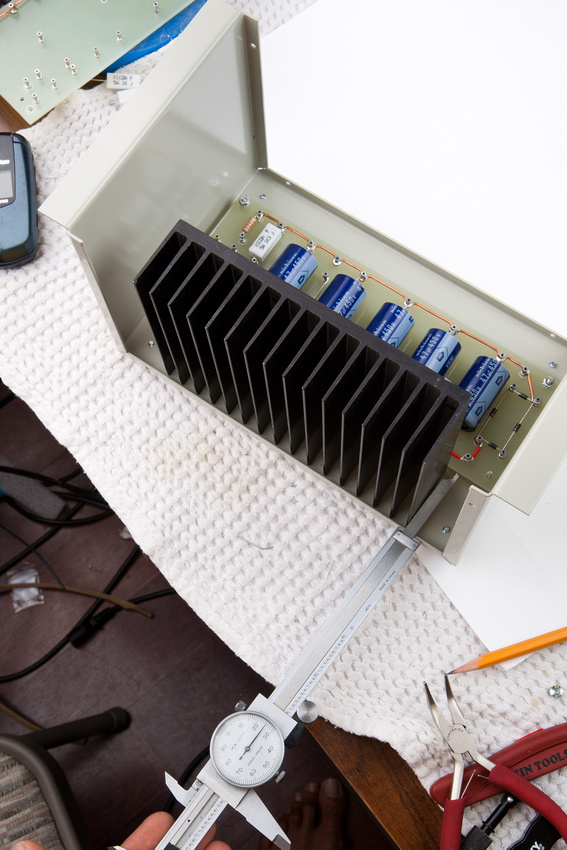
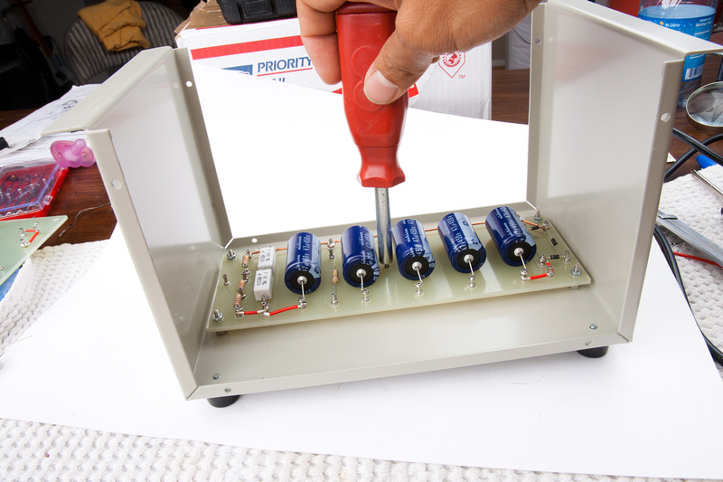
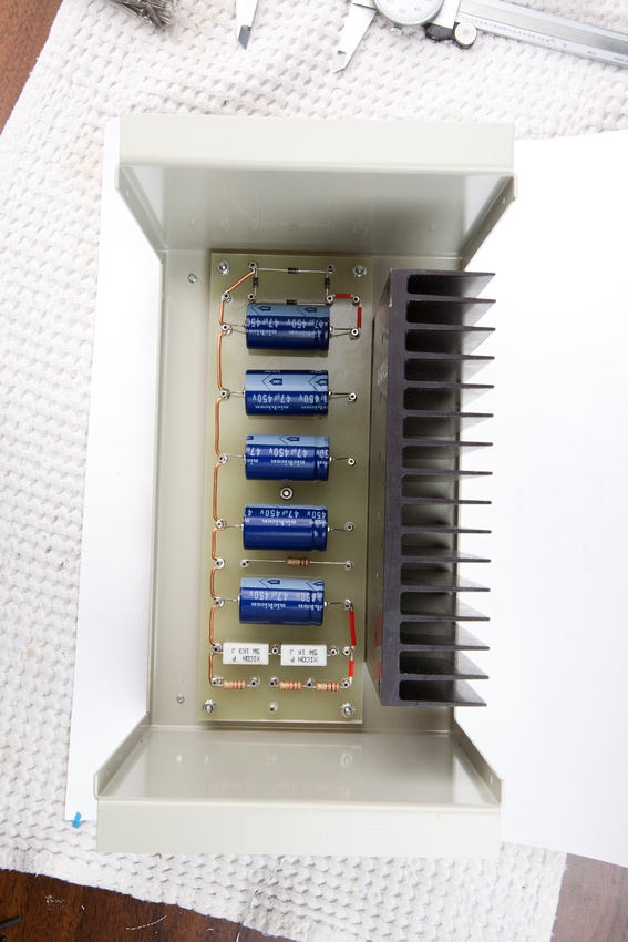
First, I need to determine exactly where I want to place the heatsink.  I use my dial calipers for precision and decide to simply place it center on the enclosure and flush against the side of my turret board.

p1039398735-4.jpg


Here I use the caliper to check how straight my turret board is mounted in relation to the enclosure edge.

p645070256-5.jpg


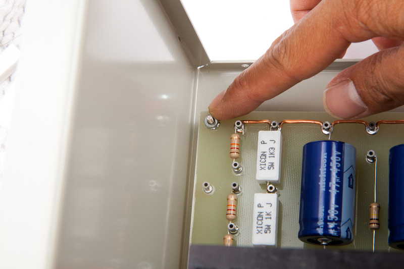
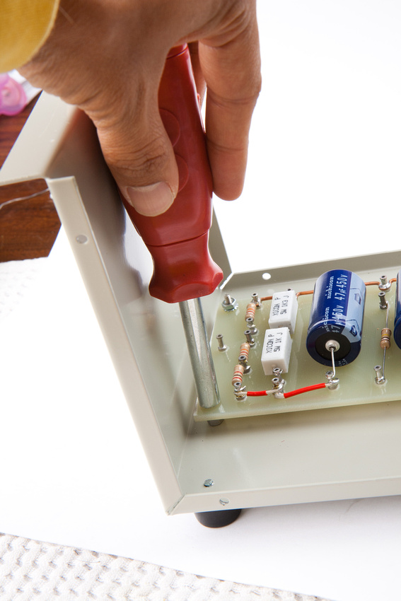
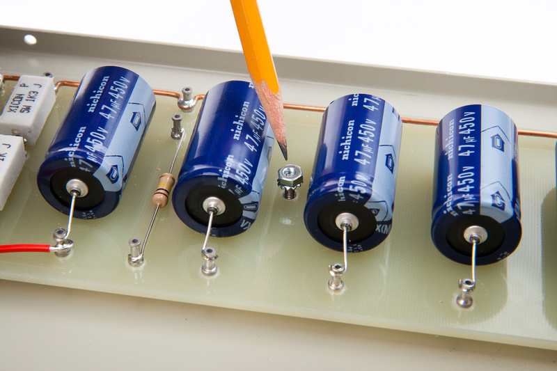
There is a little bit of slop on the turret board which is good since I can align it perfectly with the enclosure.  I install locking nuts to firmly secure the turret board and line it up to the best of my ability.

p420258641-4.jpg


p158964886-5.jpg


p399585579-4.jpg


p246109898-4.jpg


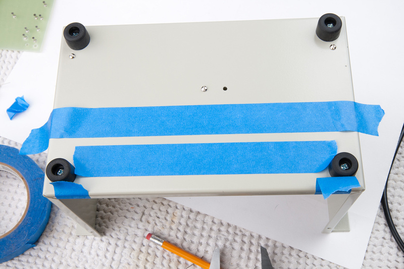
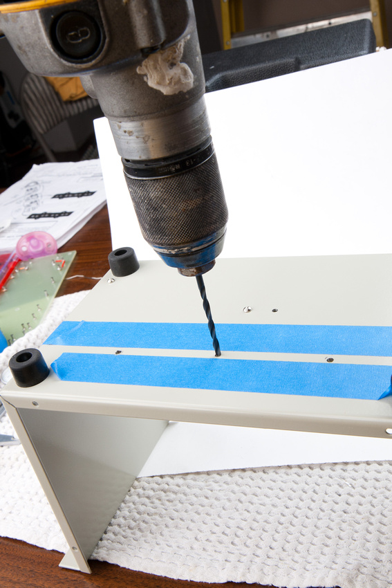
A little bit of measure and some simple math help me mark the exact position of the heatsink on the bottom of the enclosure.  This is the position I will be drilling from, and the blue tape allows me to visualize my target area during the exciting drilling operation.

p143560413-4.jpg


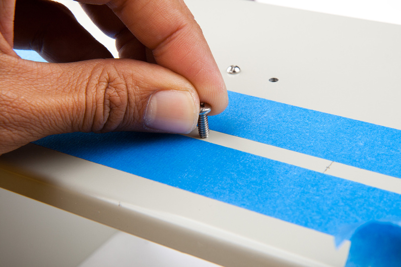
The goal will be to place this 1/2" length 6-32 screw precisely into the center of the heatsink body.

p114338799-4.jpg


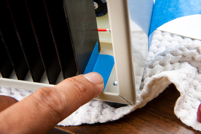
With final position determined, I tape the heatsink so it does not move from side to side.

p527090094-4.jpg


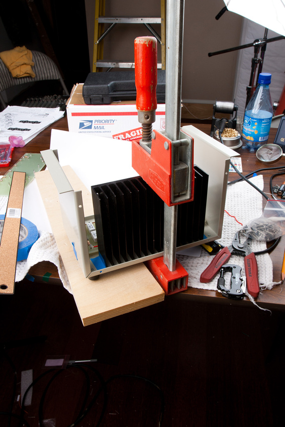
and clamp it securely to the enclosure with some force.  I need for it to remain in position while I drill through the touch steel enclosure and deep into the aluminum heatsink with a hand drill.

p206295443-5.jpg


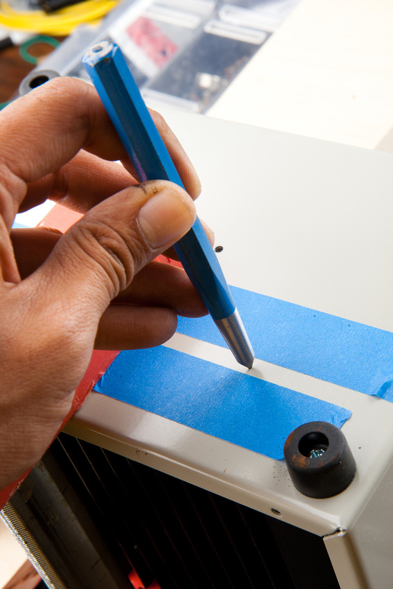
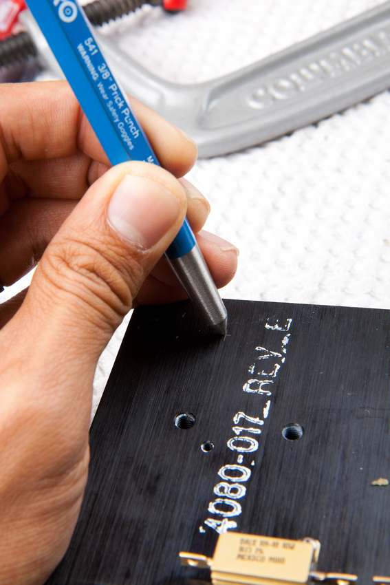
Having determined my drill locations, I flip the entire mess over and center punch for the drill hole.

p152193313-5.jpg


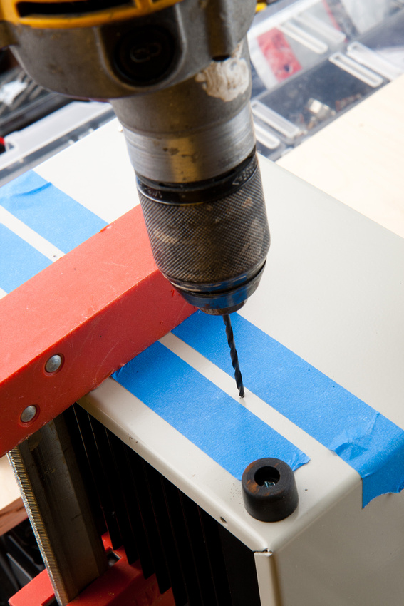
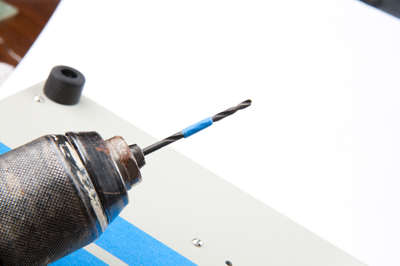
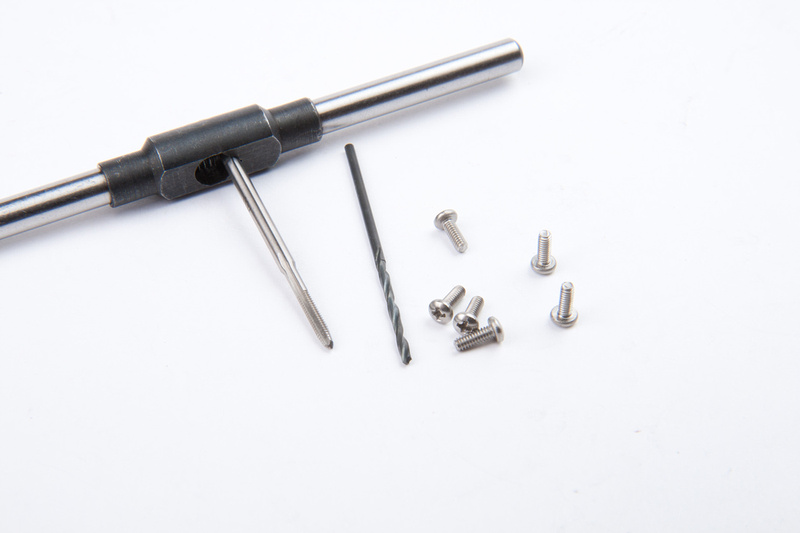
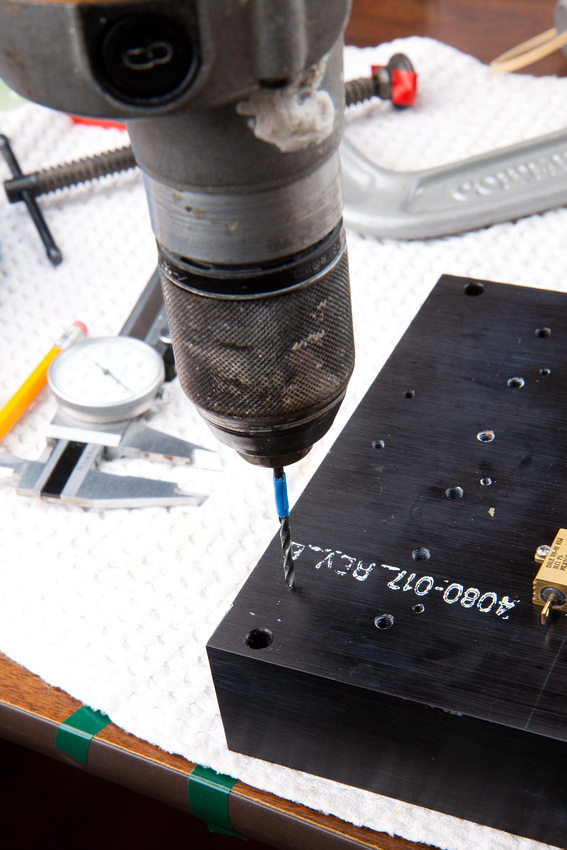
And the moment of truth.  This is a number 36 drill bit to tap for 6-32 threads.

p190697366-5.jpg


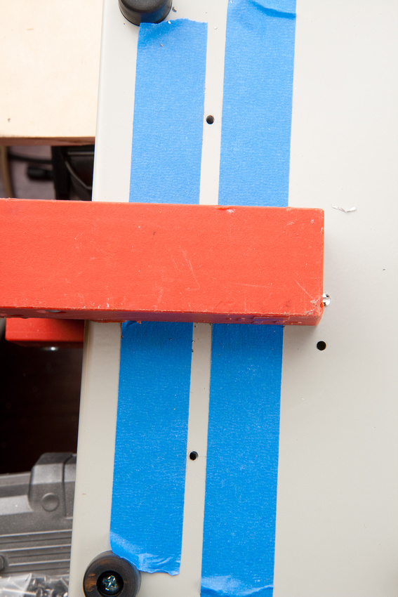
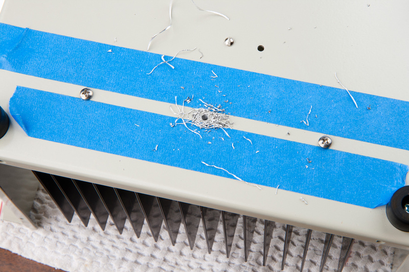
I am compensating a bit because I found the heatsink to be slightly warped, and the outsides curve towards the outside of the enclosure body a little bit.  In order to hit center, I had to compensate a little towards the outside with my drill holes.

p395232085-5.jpg


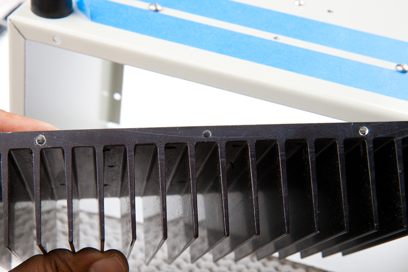
And, as for hole position on the heatsink, I could not have hoped for better.

p312978612-4.jpg


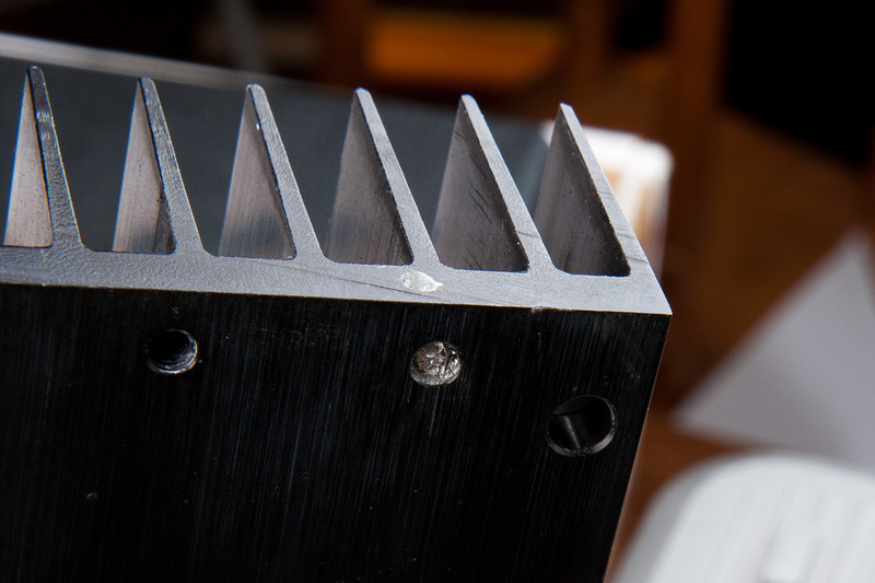
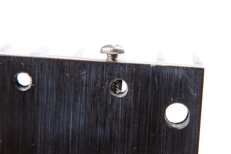
Unfortunately for me, I used the wrong side of the heatsink and it had pre-existing machine holes.  My chosen drill location accidentally took me straight into these. . . on both sides.  when I pushed into them, I thought I may have severely mis-judged my drill point, but a closer look revealed that I had simply gone into an empty spot in the heatsink.  It was all very exciting.

p186774410-4.jpg


p129765400-4.jpg


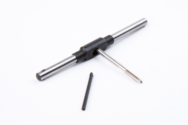
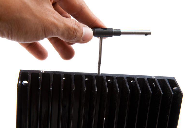
Next, I pull out my 6-32 tap.  For another project (the 51X PSU), I had originally thought I would have to do a bit more fabrication, so I purchased a few common drill bits, taps, and dies in sizes I thought would be most useful.  I did not use these for the 51x PSU project, but now I'm glad I have them on hand.

p199447790-4.jpg


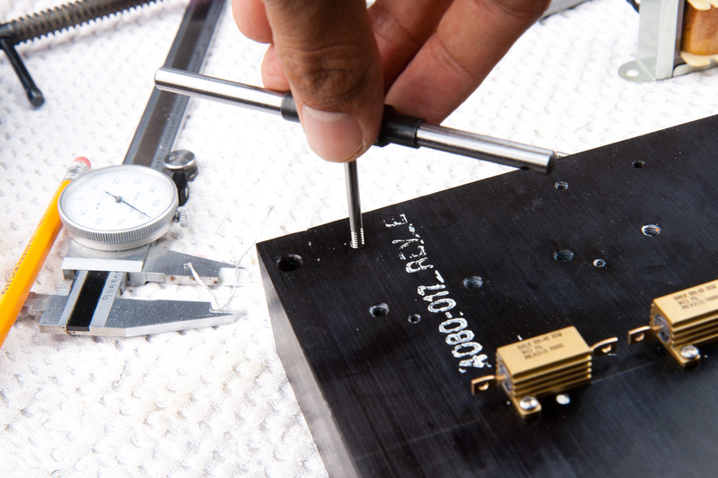
And I'm tapping.  It's important to not force the tap.  Go in a little bit and back out. . . go in a little more, back out.  Clean the debris out of the hole you are tapping often.

The result.  . . it could have been much worse.  I still have a significant amount of threads in solid metal.  The pre-existing hole caused my hand drill to wander a little diagonal, but it seems to be holding threads fine.

p536646897-4.jpg


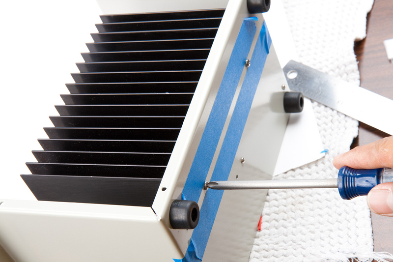
Next, use a #29 drill bit to open up the holes in the enclosure to allow the machine screws to freely pass through the enclosure and thread into the heatsink.  So I throw the heatsink in and tighten the screws.

p11778673-4.jpg


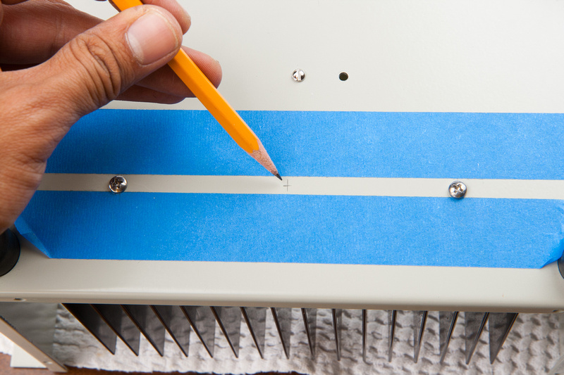
Now, with the heatsink secured, I do not need to use the clamp anymore and can mark my center hole which incidentally does not run into a pre-existing hole.  So this one should have full threads if I can drill it straight.

p134645432-4.jpg


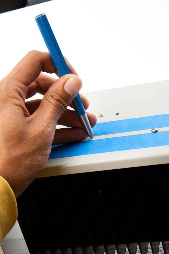
Center punch. . .

p116239434-5.jpg


tape marks my drill depth.

p57290871-4.jpg


And it's looking good.

p369102245-4.jpg


p359338858-4.jpg


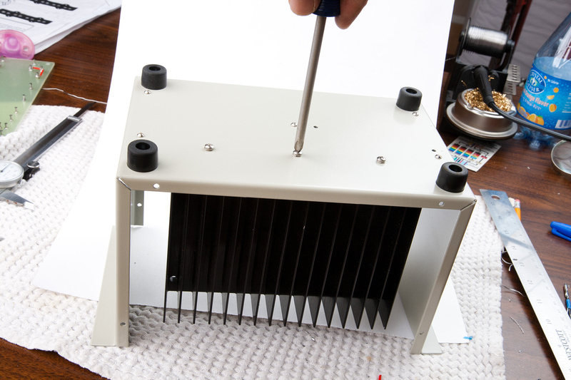
Tap the threads.

p247274328-4.jpg


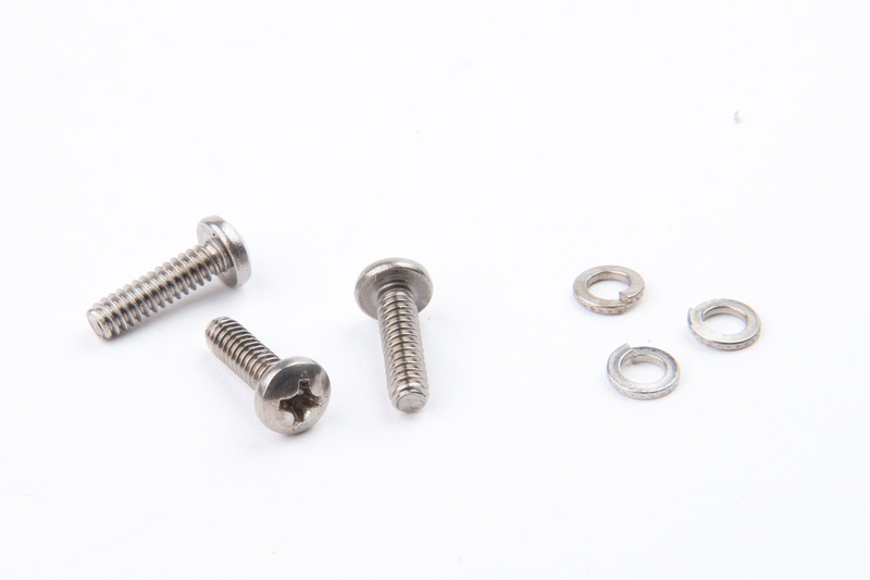
Locate final hardware. . . 7-32 screws and lock washers.

p359376257-4.jpg


One more thing .  . . I open up the enclosure hole with a #29 drill bit.

p144254063-5.jpg


and install the screw and lock washer.

p419275065-4.jpg


Humans win!

p274562789-4.jpg


p143468190-5.jpg


p448489122-4.jpg
 
I cant wait to see what you are going to cool by means of this enormous heatsink.  One of my goals in designing simple power supplies, such as I take this to be, is to minimise the amount of heat that is generated inside it.

Assuming that you put the lid on the box when finished, the heat will still be trapped inside.

Or perhaps I am missing something....

:)

David
 
The position of the heatsink lines up well with the enclosure's ventilation holes.

p59618067-2.jpg


I am not particularly electronically literate, and this is my first non-PCB build.  Certainly this PSU is not my design, but from comments in this build thread and general knowledge from others who have built the MK47 mic, some of the resistors are known to run quite hot in this design, so given that information and a lack of knowledge about how hot "hot" really is, I figured it would not hurt anything to go bigger on the heatsink and just use the cooling parts I've been tripping over in my house for a few months  :p

There seemed to be a consensus from people helping me out here that mounting 5W resistors directly on the turret board next to the capacitors as originally laid out may not be optimal long-term for this PSU.

david-p said:
I cant wait to see what you are going to cool by means of this enormous heatsink.  One of my goals in designing simple power supplies, such as I take this to be, is to minimise the amount of heat that is generated inside it.

Assuming that you put the lid on the box when finished, the heat will still be trapped inside.

Or perhaps I am missing something....

:)

David
 
I'm pretty sure he is using ioaudio's psu design, which you can read about here.
http://www.groupdiy.com/index.php?topic=41379.0

As a general rule, a PSU has to dissipate more heat for higher loads.

david-p, the 2.3k is a dummy load set to represent the mic (i.e. the mic is drawing ~45mA).
How would you improve the design to reduce heat dissipation?
Recall that the primary design requirement is excellent filtering.
 
I've narrowed my decision for microphone body for this build to the t.Bone SCT700 or the Nady TCM1050.  Do both of the bodies from these come from the Alctron factory in Ningbo, China?  The power supply on the Nady TCM1050 is very familiar looking and seems "standard" on quite a few re-branded microphones.  Even with shipping from UK, the t.bone would be the cheaper option I believe.

http://www.thomann.de/gb/the_tbone_sct700_roehrenmikrofon.htm

I wanted to check and see if the quality of the mechanicals on the t.bone are good.  I noticed ioaudio used this for his example build.  I'm not particularly interested in EXACT U47 replica or look.  This is my DIY mic, and the sonics will ultimately determine it's worth to me.  I'm just looking for solid design, reasonable headbasket, decent finish, and fairly good machining precision in the donor microphone body.  If the Nady is better than the t.bone, I'm ok to pay a little extra for some quality, but if the shells are all the same, I'll go with the cheaper option.  Oh, I guess another important factor would be the product actually gets to me this time  :p.

I am pretty set on the Beesneez K7 capsule available state-side here:

http://www.vintageking.com/BeesNeez-K7-Capsule

or direct from Australia here:

http://www.beesneezmicrophones.com.au/store/index.php?_a=viewProd&productId=76
 
Chunger,
This is taken from the Recording Hacks website
"The TCM1050 is a rebadged Alctron HSGT-2B"

I used a T-Bone for my build and it worked out great. You should consider useing an Amphenol connector on the mic side. It's a lot better than the standard 7 pin XLR and cheaper and easier to implement in the body than a Binder.

Mouser Part #
http://www.mouser.com/Search/ProductDetail.aspx?R=T_3477_000virtualkey52360000virtualkey523-T3477-000
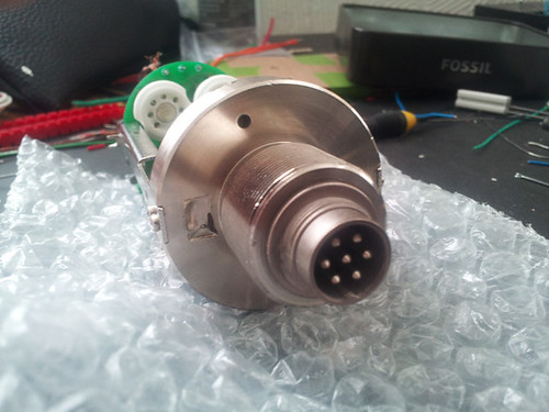


I took the 7 pin XLR out and then bored the hole to accept the Amphenol plug. After soldering the wires on, I used JB Weld to adhere the end in place.

Dave
 
wave said:
Chunger,
This is taken from the Recording Hacks website
"The TCM1050 is a rebadged Alctron HSGT-2B"

I used a T-Bone for my build and it worked out great. You should consider useing an Amphenol connector on the mic side. It's a lot better than the standard 7 pin XLR and cheaper and easier to implement in the body than a Binder.

Mouser Part #
http://www.mouser.com/Search/ProductDetail.aspx?R=T_3477_000virtualkey52360000virtualkey523-T3477-000


I took the 7 pin XLR out and then bored the hole to accept the Amphenol plug. After soldering the wires on, I used JB Weld to adhere the end in place.

Dave

I think I read on JB Weld's website that it doesn't bond well to plastics. I was looking up PVC compatability myself.
Is there a set screw on the Amphenol? If not, could one be implemented? I would think any sort of epoxy on the output jack would make repairs difficult to impossible. I do like those thick pins, though. There has got to be way to set those Amphenols without epoxy.
I'll admit I don't find the 7-pin XLR's to be the most sturdy connector, but, if used with care, they shouldn't break on you.  Never force the connectors together, and try to understand how they fit together mechanically so, when things do get bent out of shape, you can fix it easily. If this level of care is not an option (i.e.- renting out, borrowing out, or letting other "producers" use your mic), the Amphenol may be the only option.

-James-
 
James,
Dany implemented the set screw with the amphenol connector on his U67 proto hes working on so yes it can be done.

Dave
 
dmp said:
I'm pretty sure he is using ioaudio's psu design, which you can read about here.
http://www.groupdiy.com/index.php?topic=41379.0

david-p, the 2.3k is a dummy load set to represent the mic (i.e. the mic is drawing ~45mA).
How would you improve the design to reduce heat dissipation?
Recall that the primary design requirement is excellent filtering.
Is this 45mA for the anode current?  If so, I run the tubes in my mic amps 100x lower -- about 500 µA, as the C12 and U47 circuits do.

Most of the current (c. 350mA, I think) with the 6072-type of tube goes to the heater, and this will produce some heat in the PSU, but in my experience nothing that requires a large heat sink. I use a small heat sink (floating in the air) for the 7806 that I use for the heater regulation.
I bought a box like Chunger's to go with my EQU47 build, but soon found that it was too large and too inconvenient to make large holes in.  I found a smaller box: a tight fit, but more than adequate and still had a hard job cutting the holes!

The AP460 and the similar Aurycle model have even smaller PSUs that work really well, as long as you bring the HT down to 120v, and dont leave it at 175v, or more, as delivered.

David
 
wave said:
James,
Dany implemented the set screw with the amphenol connector on his U67 proto hes working on so yes it can be done.

Dave

Yep, I saw that a little too late. Those thick pins look so much more stable. I'll try it out next time I need a 7-pin connector.

S
david-p said:
The AP460 and the similar Aurycle model have even smaller PSUs that work really well, as long as you bring the HT down to 120v, and dont leave it at 175v, or more, as delivered.

David

Speaking of PSU's, does anyone know where to purchase a 9 polar pattern PSU like the ones for the Apex 460/Nady TCM1050 by itself? I'm building a Telefunken USA R-F-T clone and they use a similar PSU. Thanks. Back to thread at hand...
 
I'm actually working with a business partner on the ground in China to source non-logo'd microphones for this project from the Alctron factory in Ningbo, China which OEM's for a few mics popular for modding.  They will come with power supplies and at least for my mk47 build, the supplies may not be needed so I should be able to off-load minimum 1 but perhaps several 9 position polar pattern PSU's of the standard Alctron variety.

I really am upset enough about the Equinox order and non-customer service follow-up that I'm willing to put down quite a few thousand dollars to make a functional high-quality alternative available.
 
HellfireStudios said:
Speaking of PSU's, does anyone know where to purchase a 9 polar pattern PSU like the ones for the Apex 460/Nady TCM1050 by itself? I'm building a Telefunken USA R-F-T clone and they use a similar PSU. Thanks. Back to thread at hand...

Dave Thomas at AA Microphones sells one on his parts page for $90:

http://www.aamicrophones.com/parts.htm

 
david-p said:
dmp said:
I'm pretty sure he is using ioaudio's psu design, which you can read about here.
http://www.groupdiy.com/index.php?topic=41379.0

david-p, the 2.3k is a dummy load set to represent the mic (i.e. the mic is drawing ~45mA).
How would you improve the design to reduce heat dissipation?
Recall that the primary design requirement is excellent filtering.
Is this 45mA for the anode current?  If so, I run the tubes in my mic amps 100x lower -- about 500 µA, as the C12 and U47 circuits do.

Most of the current (c. 350mA, I think) with the 6072-type of tube goes to the heater, and this will produce some heat in the PSU, but in my experience nothing that requires a large heat sink. I use a small heat sink (floating in the air) for the 7806 that I use for the heater regulation.
Don't confuse a U47 PSU (U47N, NG, ioaudio's design, etc.) with other tube mic PSUs.

It's about getting 105V/45mA from ~250V with brute force filtering (C-R-C.... or C-L-C-R....), no regulation.
The resistors will produce some heat and a heatsink will help though in the original Neumann design the resistors were hanging in mid air....
 

Attachments

  • NG_1.jpg
    NG_1.jpg
    108.2 KB
OK. . . a lot of hacking today.  The great problem with DIY I've found is that you have to do it yourself.

One clarification note.  In a discussion with ioaudio, he mentioned that this heatsink is WAYYYYY overkill for this powers supply.  We are dissipating 5W of heat here.  Simply screwing the chassis-mounted resistors to the bottom of the enclosure would be more than sufficient for this power supply.  But, since I heard the word "hot" and went into my typical DIY panic, I will now have a very cool running PSU.

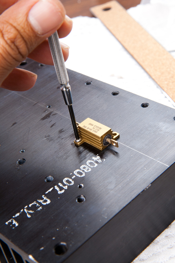
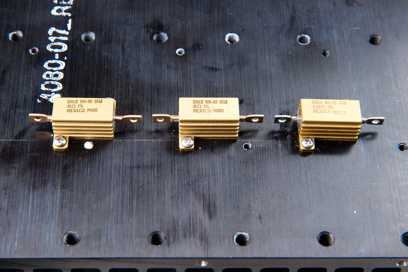
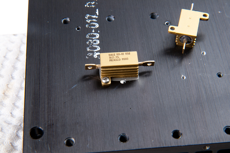
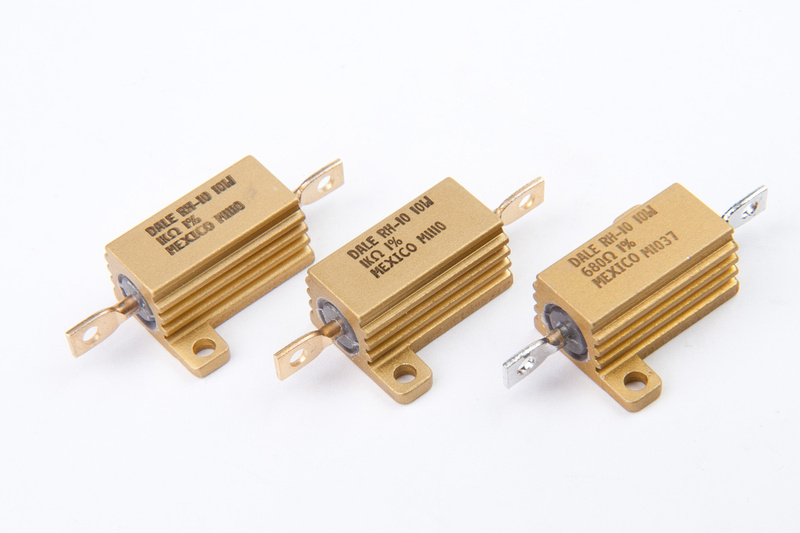
On with the build.  My new resistors came in from the nice folks at Mouser.  10W chassis mounted type.

p449986358-4.jpg


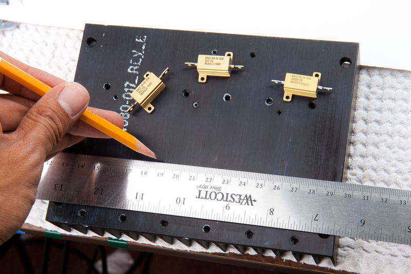
I lay out my components on the back of the heat sink to see if there is a logical way to position everything.

p291870329-4.jpg


I make a line where I hope to position the resistors.

p64583755-4.jpg


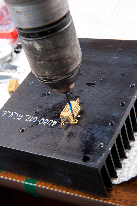
and pull a #51 bit, some 2-56 screws, and a 2-56 tap.  Note:  M2 screws would also fit here.  They are a little smaller and the threads are finer, so I thought for aluminum, the 2-56 would work better.  Sidenote:  I found a GREAT fastener store right around the corner from me that has every fastener I could ever need in stock along with bits, taps, dies, and most importantly, knowledgeable people to help.

p466286544-4.jpg


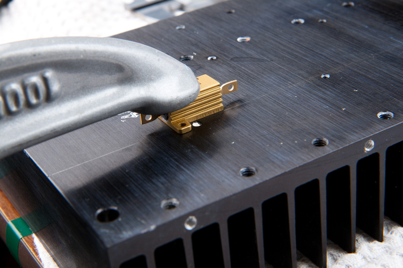
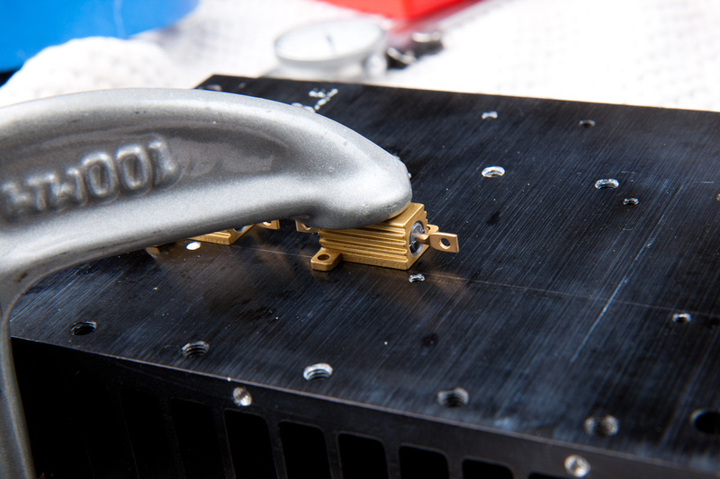
I clamp a resistor into position. . .
p45331762-4.jpg


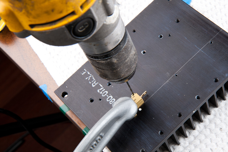
. . . and drill a hole.

p308702113-4.jpg


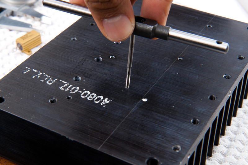
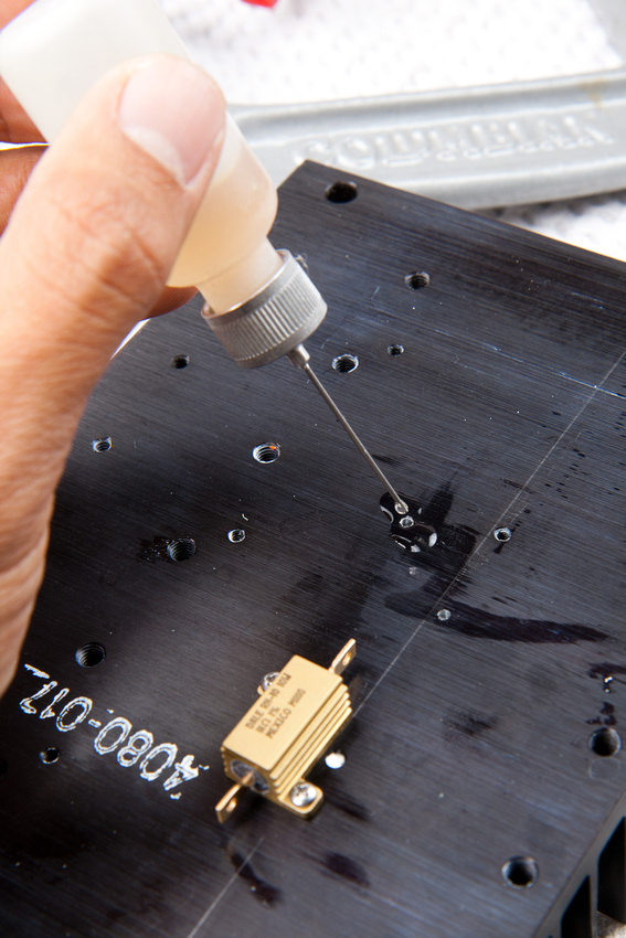
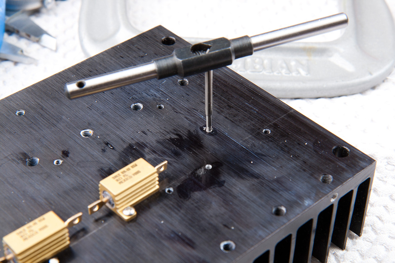
Next, I attempt to tap and quickly break my tap bit  :mad:

p431334190-4.jpg


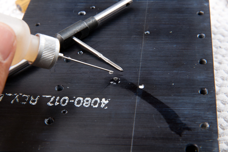
I realized that for these tiny holes, the taps are fragile, and I will have to go very slowly backing out often and feeling for binding.  Also, it is absolutely necessary to use some sort of cutting oil.  I dig out my spare tap (last one) and continue.

p240034611-4.jpg


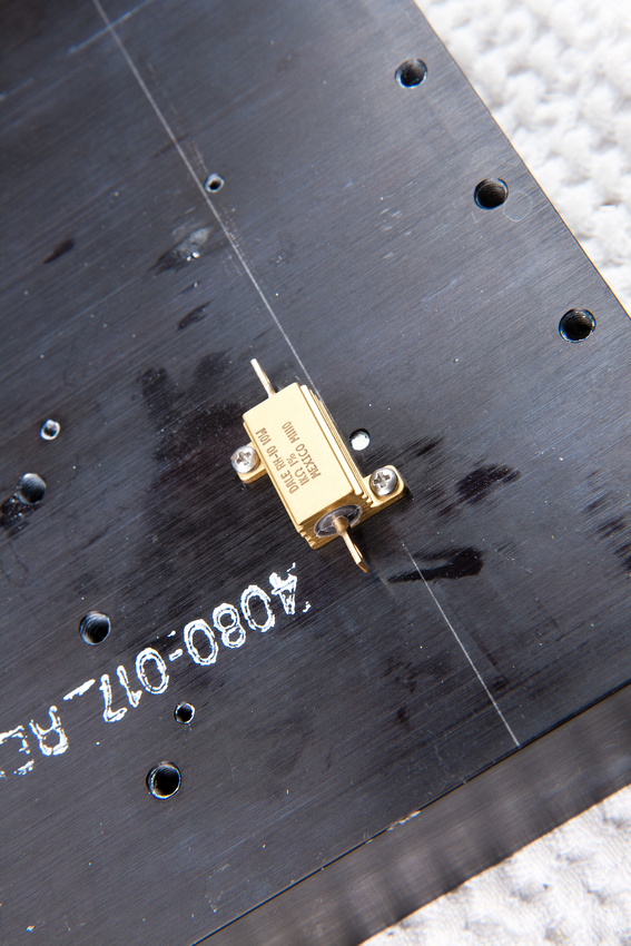
First screw goes in.
p473631187-5.jpg


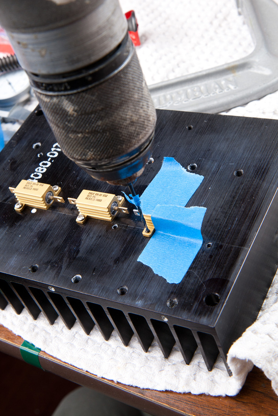
and the 2nd hole gets drilled.
p406210759-5.jpg


Poof!

p265079663-5.jpg


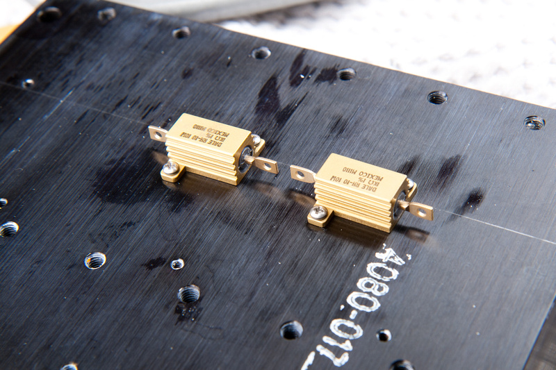
2nd resistor.

p436174934-4.jpg


p456209050-5.jpg


p180263226-4.jpg


3rd resistor.

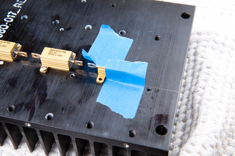
Here I decided to try and tape the resistor to the heat sink instead of clamp. . . and it worked ok.

p275482183-4.jpg


p495173480-5.jpg


p241227579-4.jpg


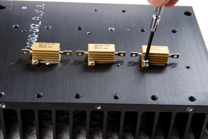
resistors in place.

p18695355-4.jpg


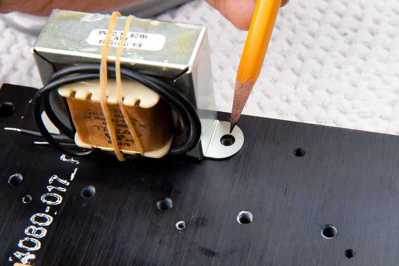
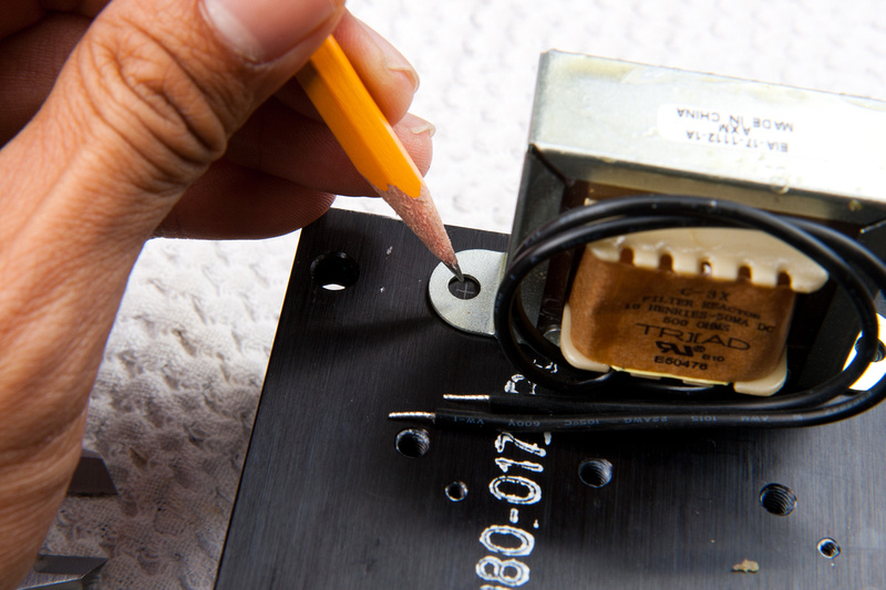
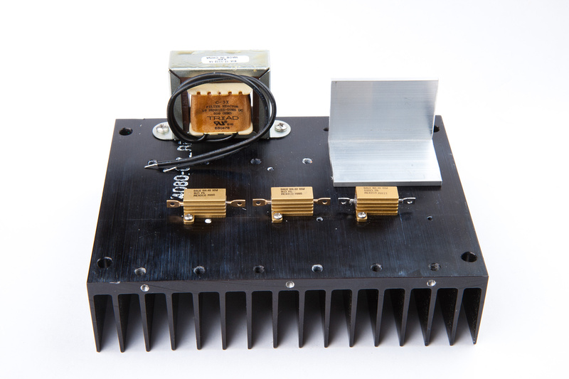
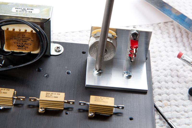
For the choke, I decide to use one of the existing 6-32 holes on the heat sink.

p423339809-4.jpg


I mark the hole for the other side carefully.

p128536001-4.jpg


center punch.

p103326157-5.jpg


and drill starting with a small bit to minimize error.

p445901653-5.jpg


follow up with the #36 drill bit and then tap for 6-32.

p174421773-4.jpg


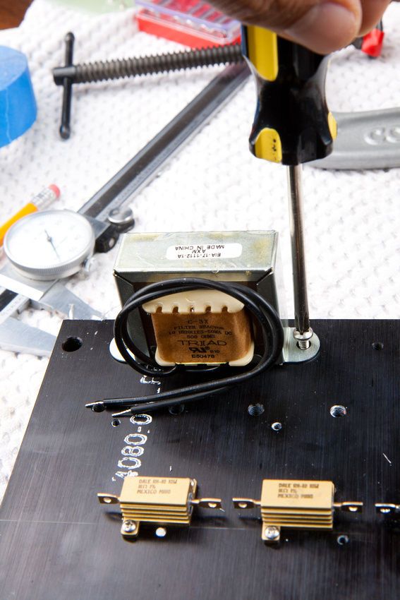
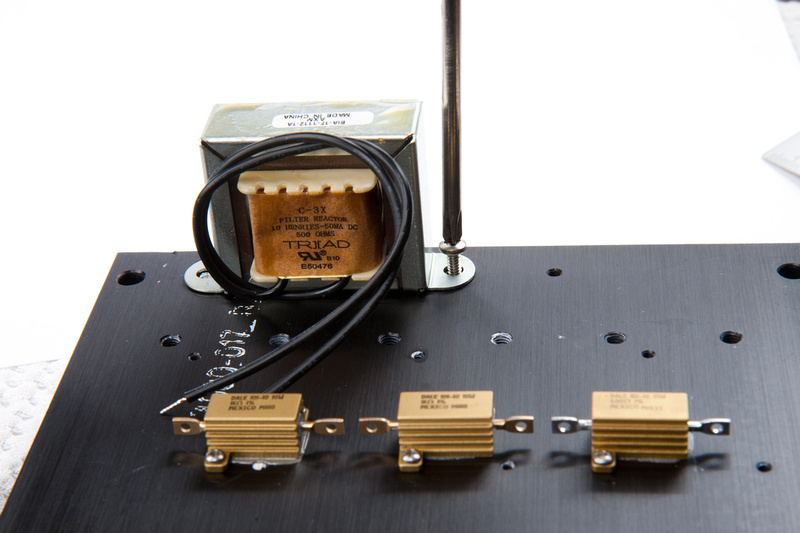
choke goes in.

p157288969-5.jpg


A quick look to see where we are.

p304527916-4.jpg


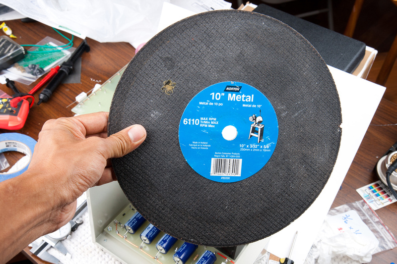
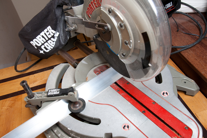
Next, I search all over the house to locate my metal cutting blade for the chop saw.

p453705341-4.jpg


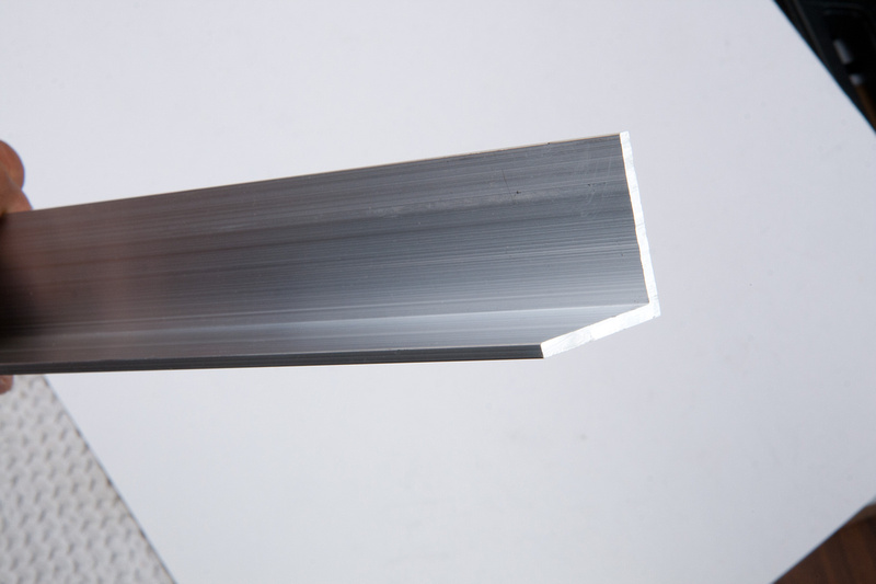
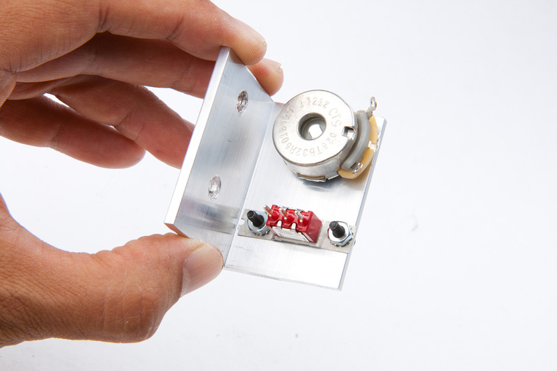
I also went to Home Depot and found this 1.5"x1.5"x.125" aluminum L bracket to mount my voltage trimmer pot and "test mode" switch.

p395836226-4.jpg


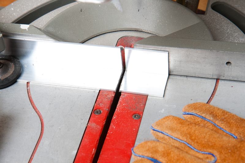
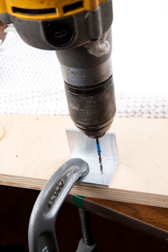
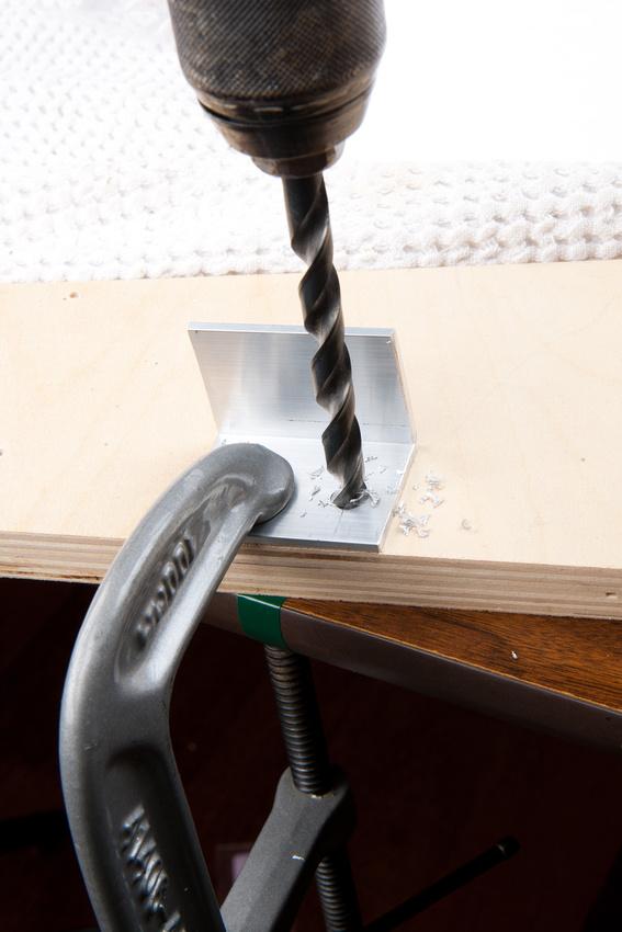
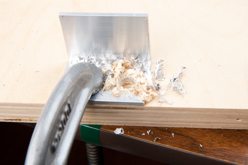
I cut a small portion for my mount.

p73346319-4.jpg


p135993846-4.jpg


And find a good place on the heat sink to mount this bracket.  I will utilize 2 existing 8-32 holes on the heat sink.

p533673493-4.jpg


mark and center punch for the potentiometer mount hole.  This will be 3/8 inch.

p61829443-5.jpg


Start out with a small hole.

p40444668-5.jpg


and follow up with my 3/8" bit.

p487664500-5.jpg


p474325354-4.jpg


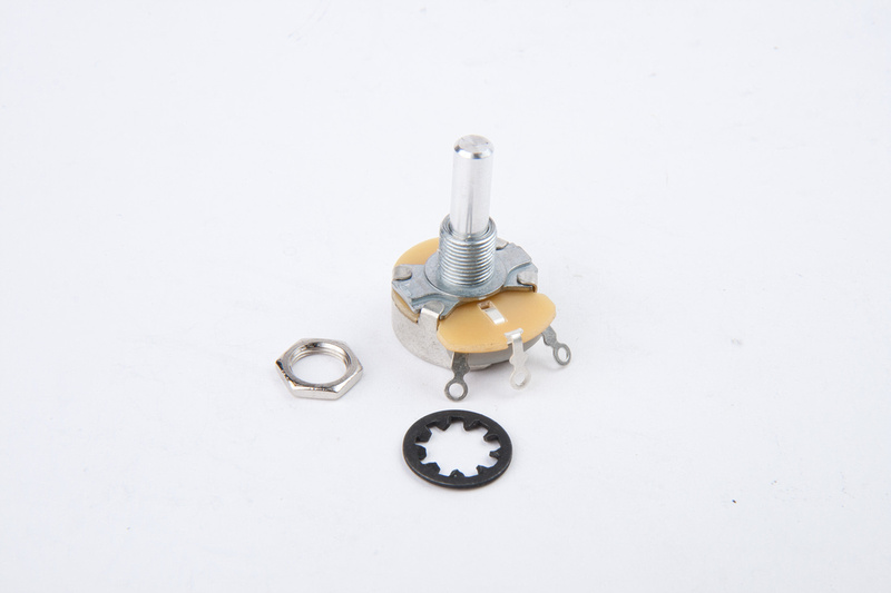
pull my 500R potentiometer.

p26983545-4.jpg


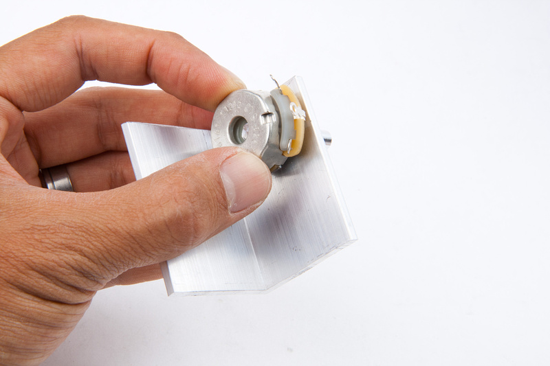
and make sure it fits.

p128152560-4.jpg


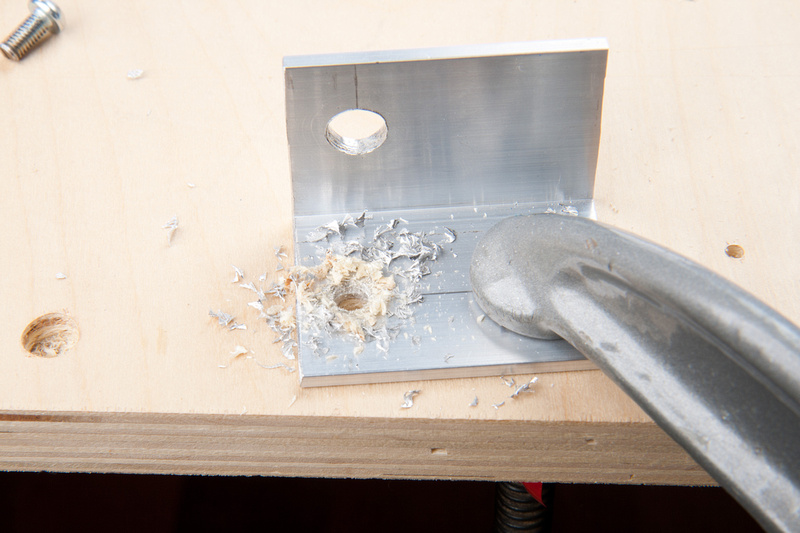
Next, I locate the pre-existing holes i plan to mount the bracket to and mark my drill locations.

and drill.

p144909488-4.jpg


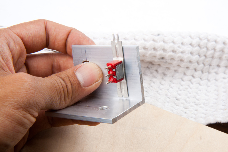
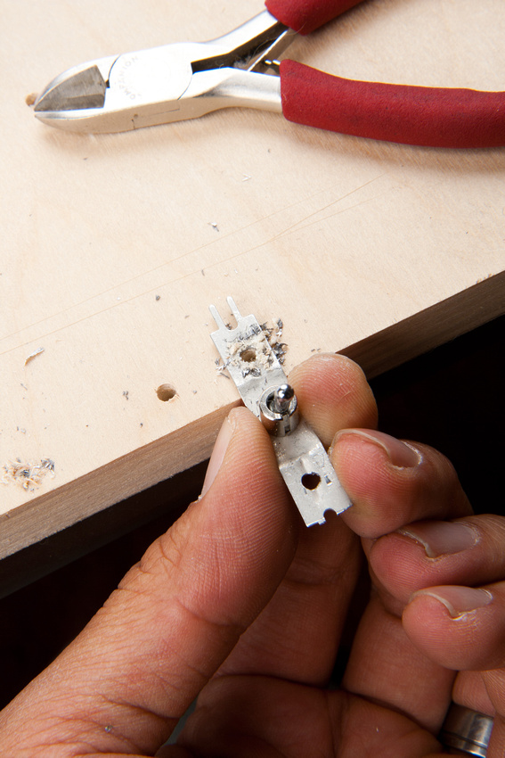
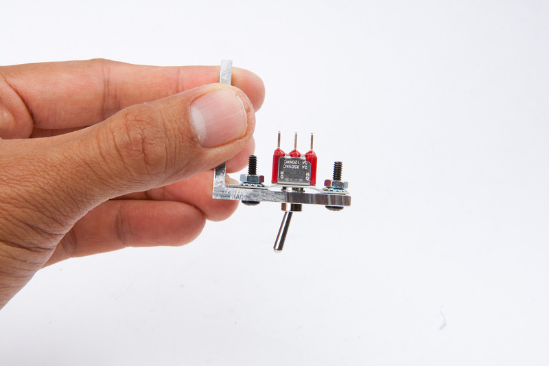
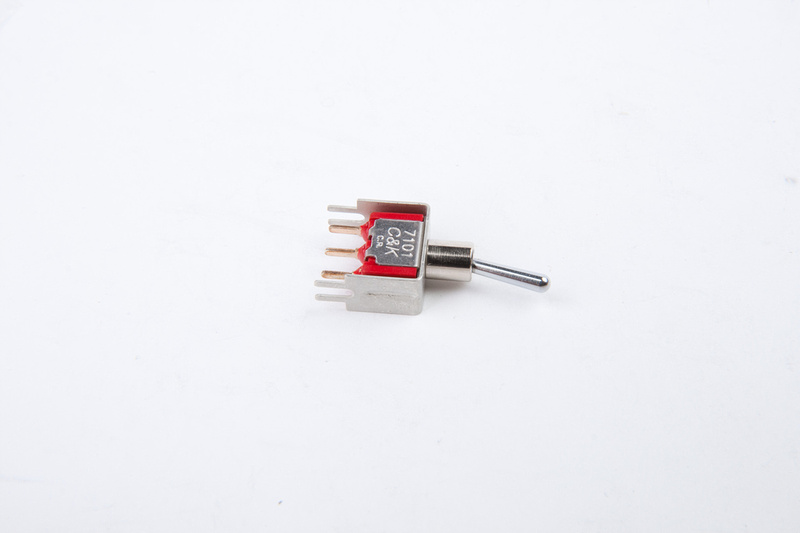
I ordered the wrong C&K switch, but I figure I can find a way to fit it in cleanly.

p50100159-4.jpg


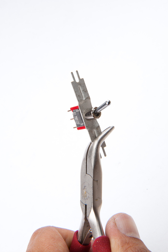
First, I bend out the side tabs.

p312770070-5.jpg


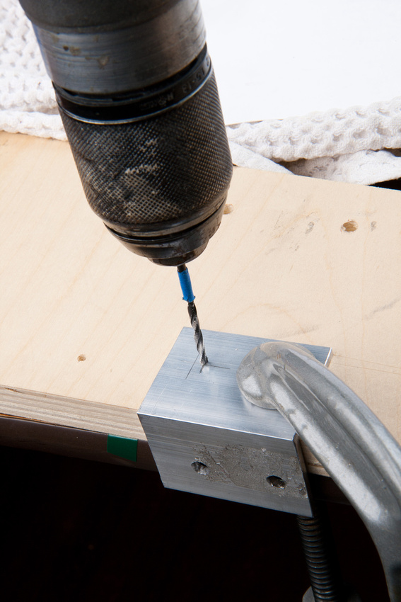
and drill the 1/4" hole for the switch to go into.  I start with a small bit for precision and then expand to 1/4".

p111599721-5.jpg


Not too bad.

p228718122-4.jpg


I have to do some initial trimming to make the switch fit.

p346708365-4.jpg


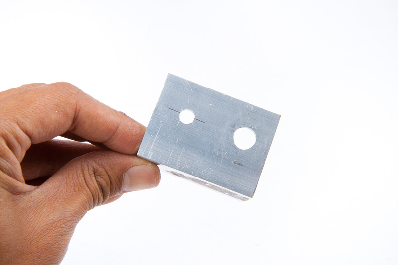
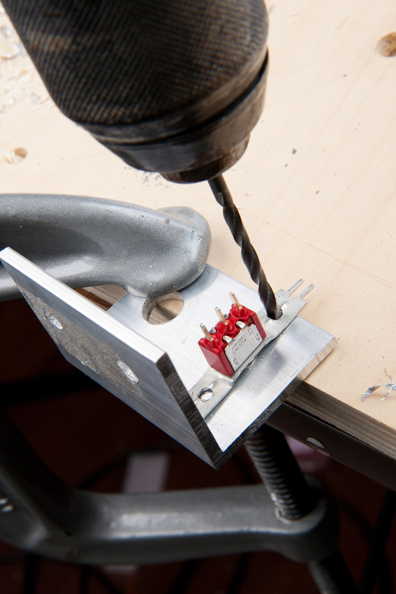
Then, I drill my mounting holes into the side tabs.

p498847888-5.jpg


and transfer these holes to the L-brackt.

p364969504-5.jpg


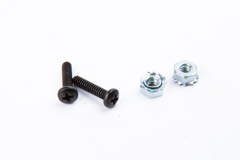
pull hardware for the switch.  These are 4-40 screws nuts with attached locking washers.

p343385284-4.jpg


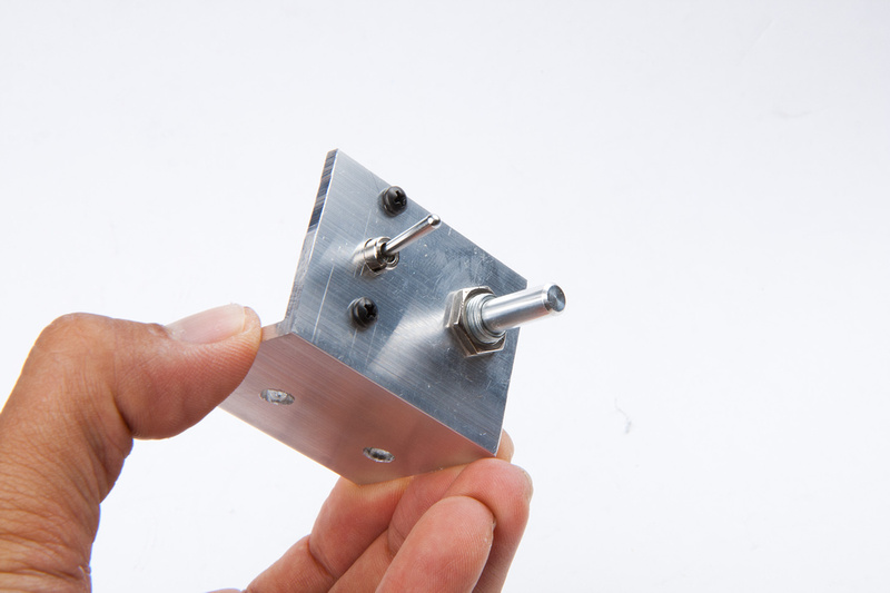
switch mounted.

p197652312-4.jpg


Pot mounted.

p97545938-4.jpg


p417676842-4.jpg


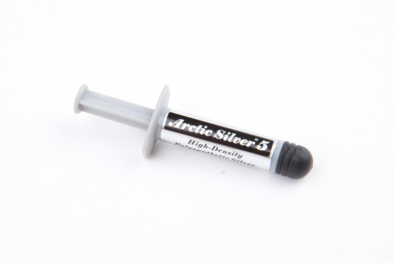
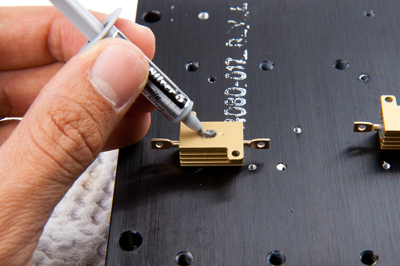
and, probably completely unnecessary, but since I'm doing overkill, I might as well go all the way.  Thermal compound.

p490761943-4.jpg


A little bit goes a long way as I prep to install the 1st resistor.

p517688978-4.jpg


p170277078-4.jpg


Final assembly of the heat sink components.

p41913471-4.jpg


p363937202-4.jpg


p111230391-4.jpg


And this is where we are tonight.

p172764634-4.jpg
 
Great stuff. I like how you "modified" the switch to work for you. For a newbie, you seem to be doing really well. Keep it up.
BTW, that line about having to do DIY yourself is hilarious.

-James-
 
Is this 45mA for the anode current?
If you look at the schematic (on the same page, linked below), you see that the anode AND the heater are being driven by the B+. There isn't a separate heater supply. This explains the high current requirement.

http://www.groupdiy.com/index.php?topic=41379.msg513821#msg513821
 
Back
Top