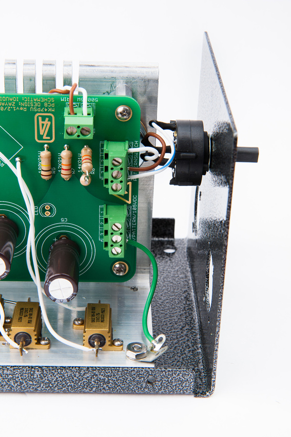
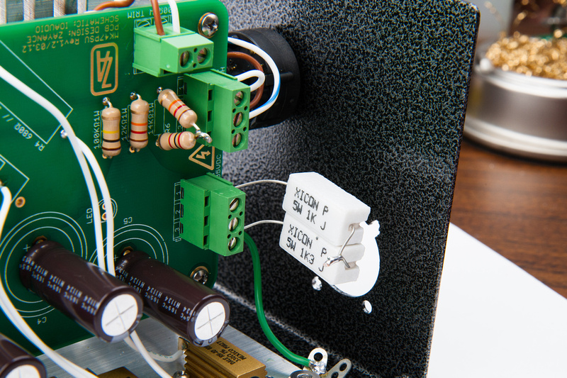
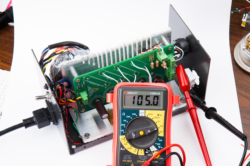
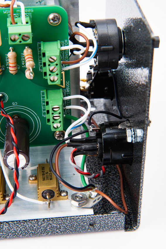
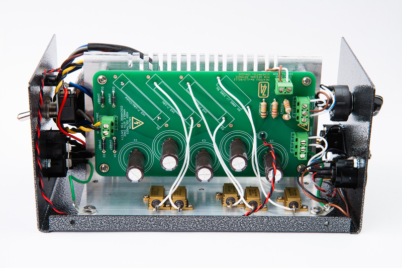
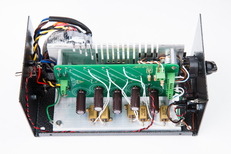
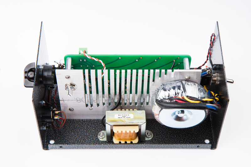
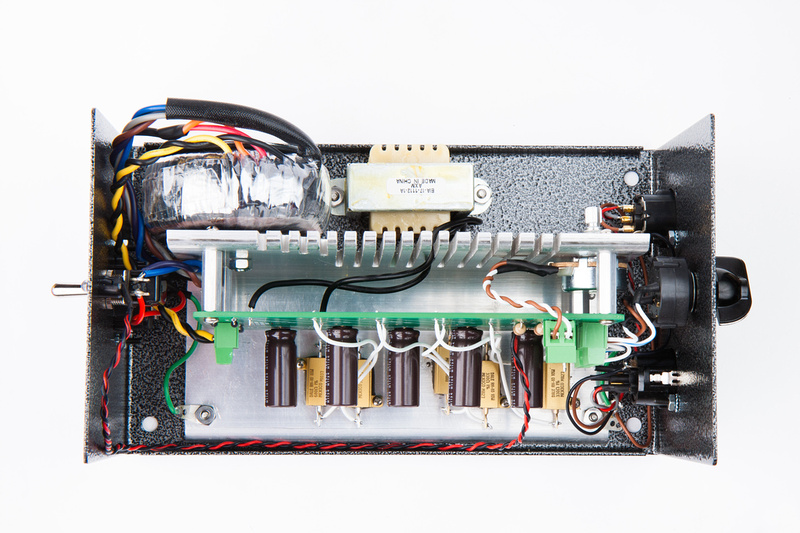
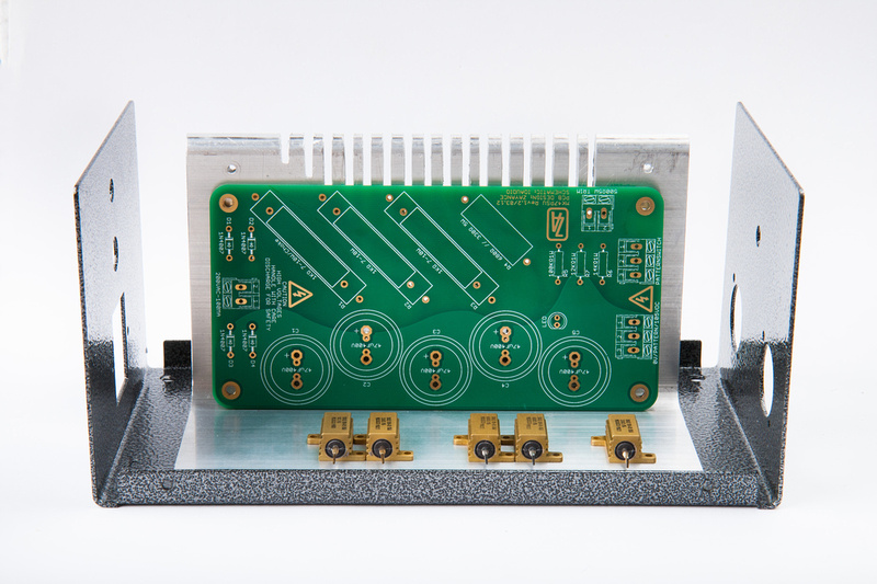
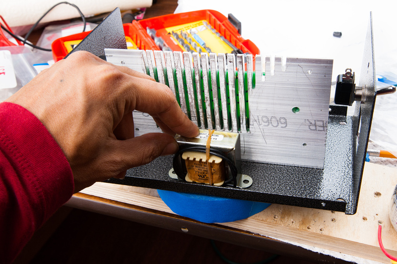
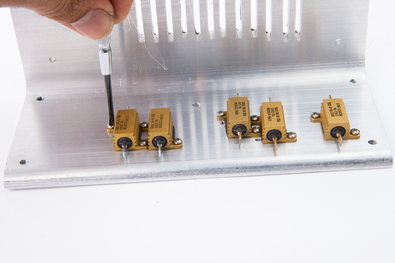
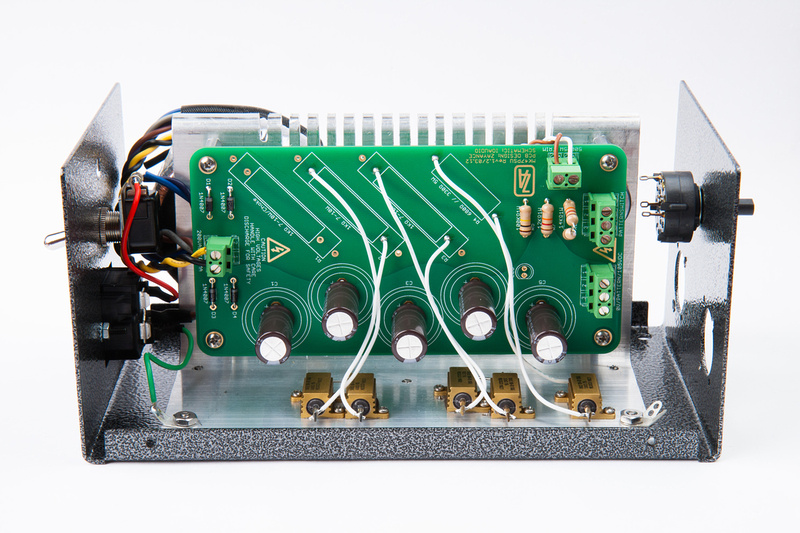
Getting on with the build a little bit, I lay out the position of my resistors. Originally, i had wanted to mount these directly on the vertical plane, but decided to make deeper cuts for my heat sinking instead, so the resistors are now on the bottom of the L-bracket. Unfortunately, I had already cut and drilled around the toroid mounting point, so I could not flip the PCB around which would have allowed for a shorter wire run between the resistors and the PCB.
Ah. . . I guess an explanation would also be in order for the number of resistors. Being as my piggy bank is a little bit broken right now due to large orders of microphones pending from China, I am not feeling particularly inclined to make another Mouser order, so I decided to cobble together the resistor values I have left over from the previous PSU.
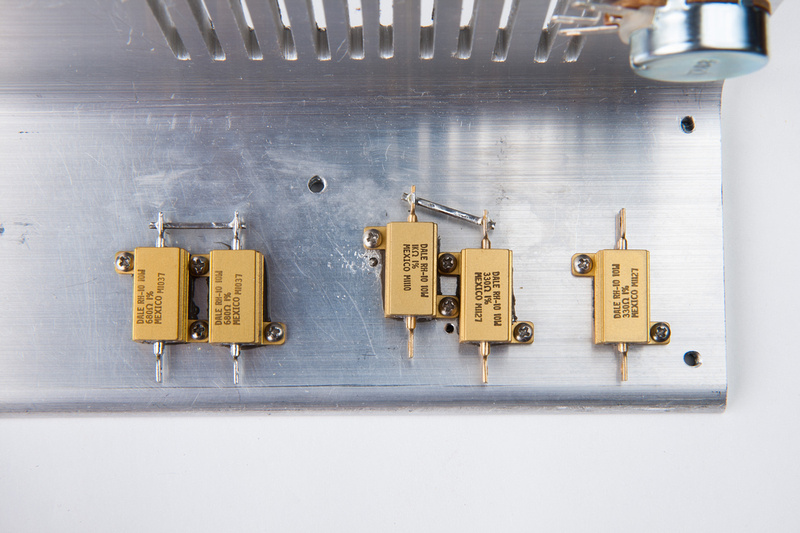
With this Triad toroid, my sequence was Choke, 1K, 1K, 1K + 1K pot. So the last stage was 2K because I had my trimmer pot bottomed out to max resistance. I decided I would try spreading out the resistors along all 3 resistor stages, so my setup for this build is:
680ohm + 680ohm , 1K + 330ohm , 330ohm + 1K pot which ends up theoretically only 20 ohms more in total than my previous PSU which trimmed out to the target voltage. .. well, almost anyways. I'm sure the math probably works differently on the front stage resistors, but I thought it would be worth a try. The hard part is drilling and tapping the mounting holes anyways. At worst, I can buy the same value resistors as the previous build if this doesn't work out. But, for now, I don't have to make another Mouser order. Silly I know.
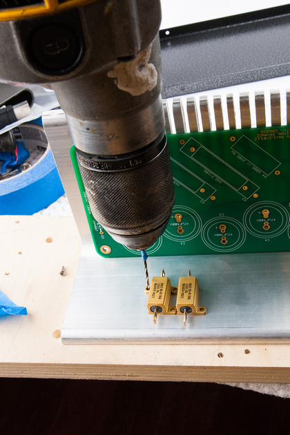
Once I determined the location of the resistors, I drilled my mounting holes. . . I'm going to tap 2-56 and drill with a #50 bit. I actually drilled with a #52 bit which may explain my problem of breaking taps. #50 bit allows for 75% thread engagement while #52 I presume allows for 100% which is not necessary for strength. I should buy some #50 bits.
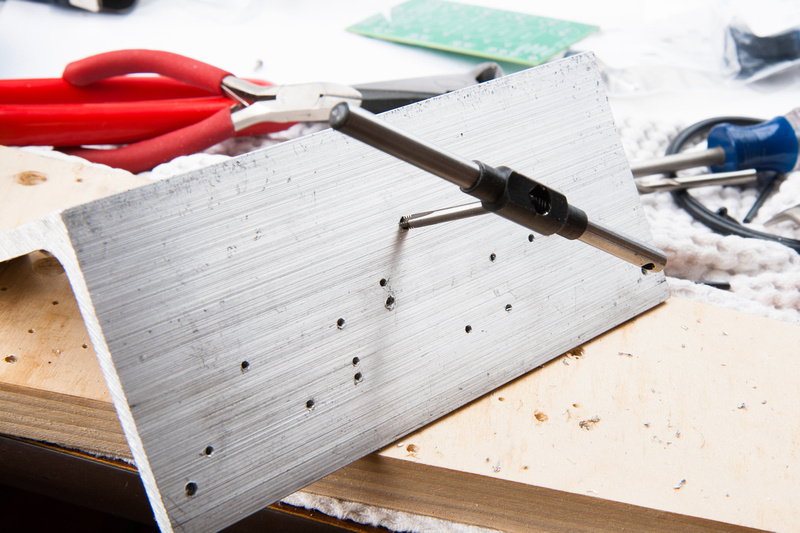
After drilling, I tap the holes. .. unfortunately for me, I went a little bit too fast with my hand tapping and sheared off my last tap in one of the holes as it was almost through. So, I had to make another trip to the screw store the next day to finish up. I also was not able to extract the tap, so I had to re-drill one of my resistors, and it is offset from the rest.
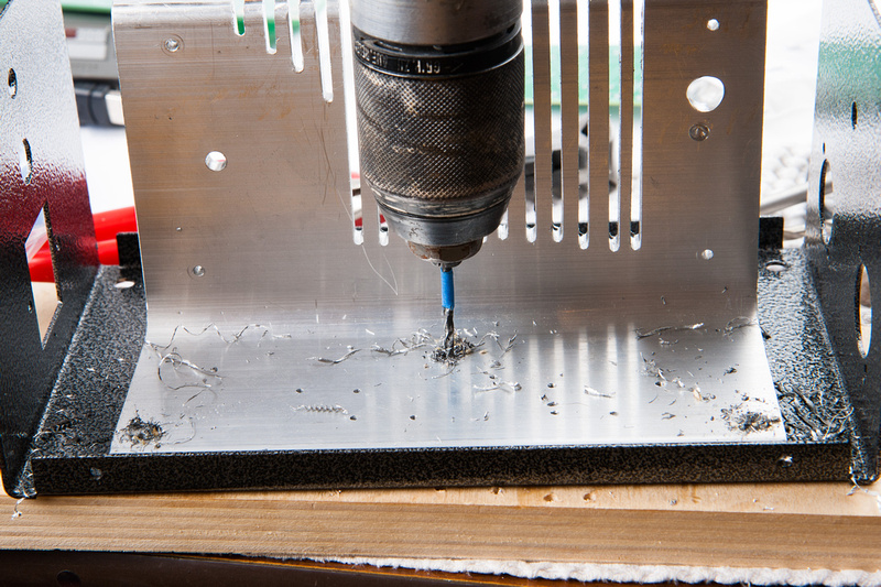
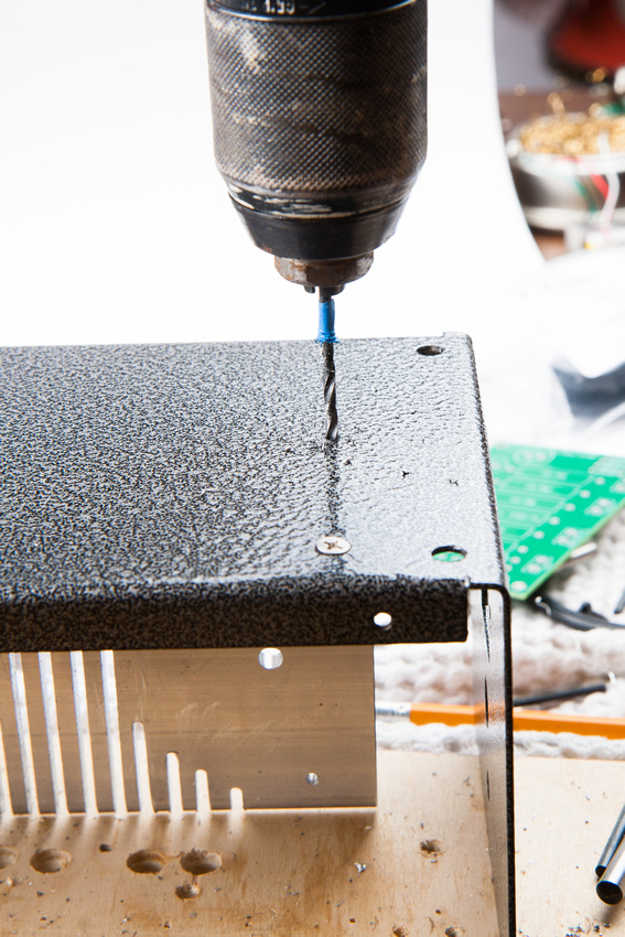
Next, I align the L-bracket, secure the assembly with clamps and drill straight through the aluminum bracket and the case. These are my mounting holes. From the inside, I am able to easily drill 3 holes with a hand drill so I do. I use a #36 bit because I will tap these for 6-32 threads.
I tap from the back side because I have better clearance for the handtool I am using.
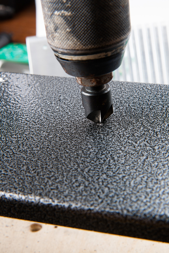
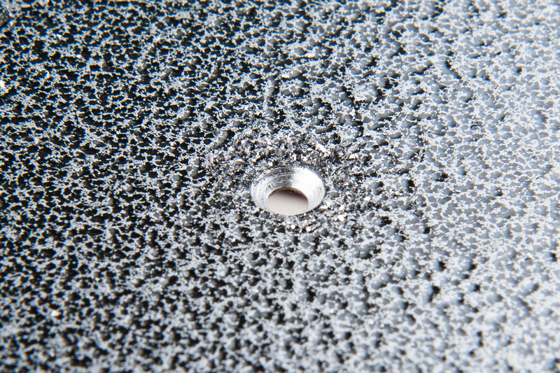
From the bottom of the case, I enlarge the holes to allow the screw to pass through and bevel the edge to mount flat head screws.
With the L-bracket secured using 3 screws, I drill my remaining 2 mounting holes from the bottom because the bracket makes drilling these impossible from the top side.
Once these holds are tapped, the L-bracket is fully prepped for final assembly.
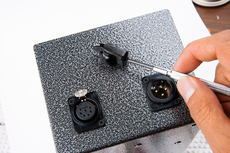
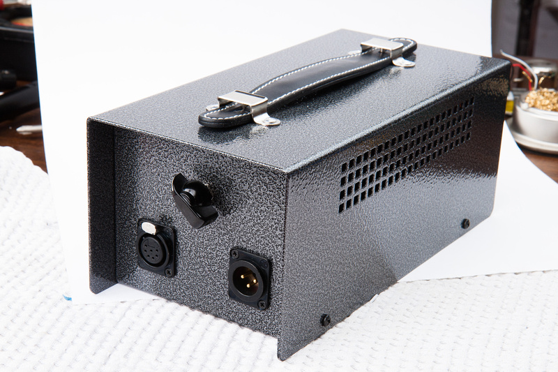
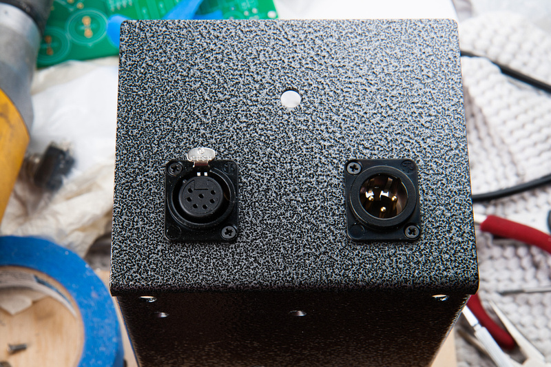
This particular case came to me as a prototyping sample because the sheetmetal on the base plate was bent the wrong direction causing the XLR holes to be in the wrong positions. I align the XLR jacks with some creative straight edge and taping arrangements and attempt to drill these holes straight.
I never seem to get these right as my drill bit wanders, but with some creative filing on the holes, I get thing to look decent from the front side.
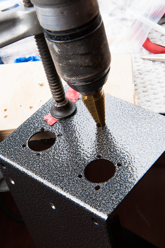
My particular rotary switch requires a larger hole than provided on the front face of the case, so I enlarge this with a unibit.
Next, I determine the final location of the choke and drill the 2 holes required for mounting this.
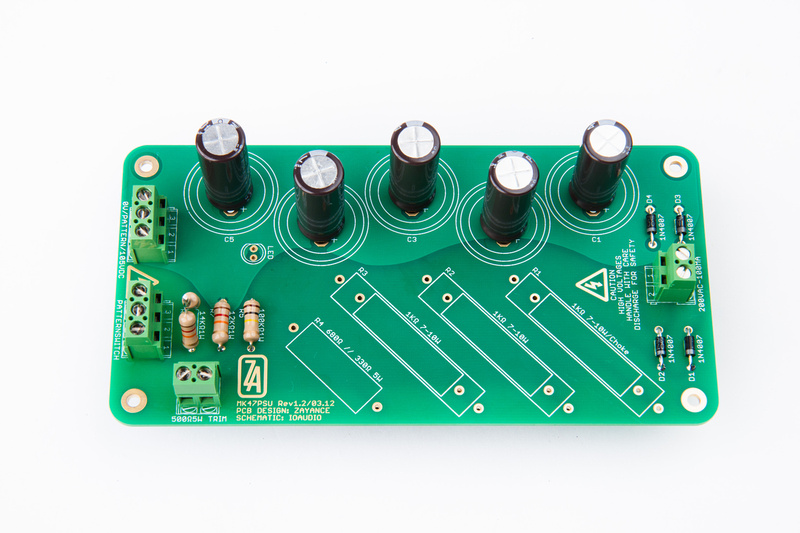
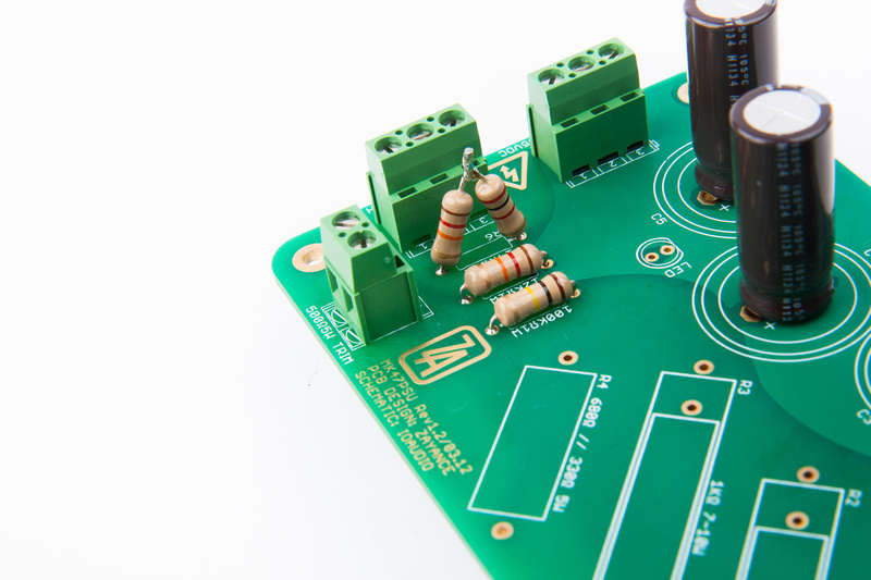
Next, I stuff the PCB. This ended up being the easiest part of the whole build as there are very few components and the design is very straight forward.
I could not locate a 14K 1W resistor on Mouser at the time I purchased my parts, so I installed a 12K and a 2K resistor in series.
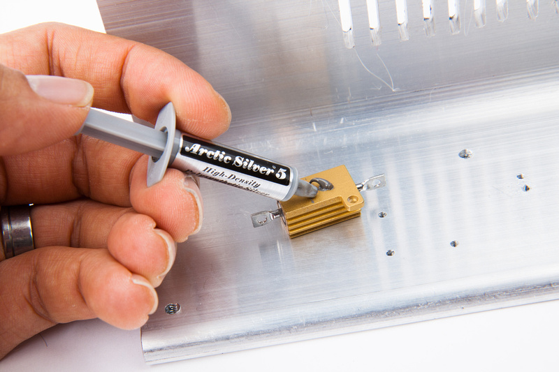
Suffering from a bit of attention deficit disorder, I jumped to installing the chassis-mount resistors. I use some thermal compount. Probably completely unnecessary but it makes me feel better about myself.
And, resistors are installed with some short 2-56 screws.
Resistors are going to be installed in series, so I decide to jumper the back side with some component cut-off ends.
Note the offset resistor and tap that is now permanently embedded in my bracket

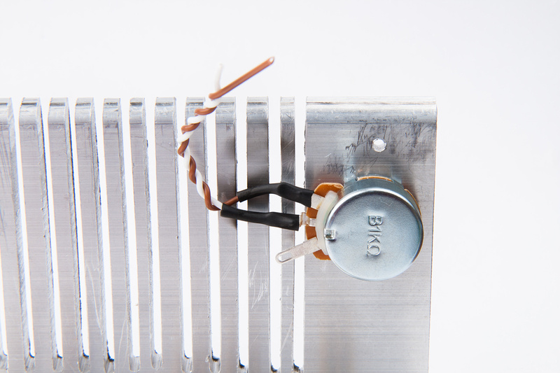
The trimmer pot is wired up with a short lead as the connection on PCB is very close to this location.
And, I install some 3/4" aluminum standoffs.
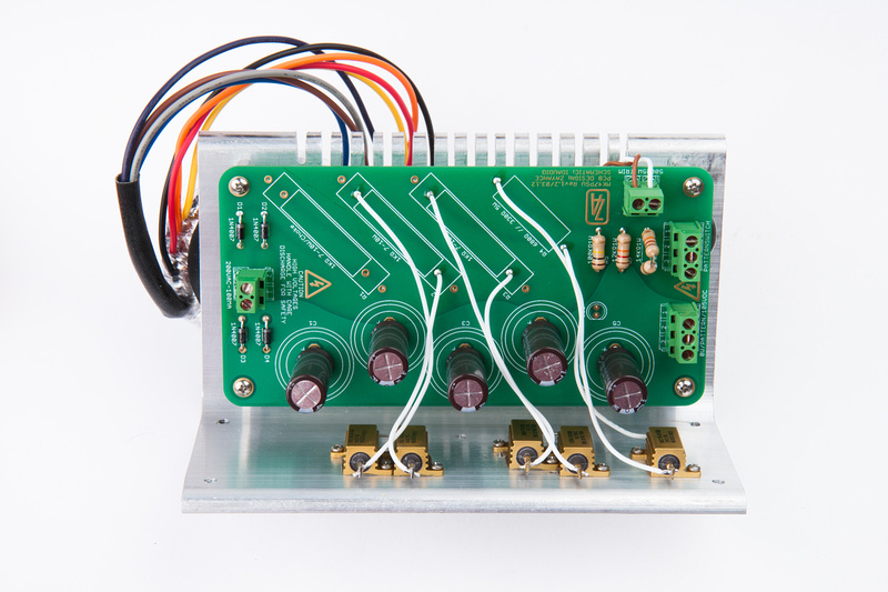
PCB is mounted and resistors wired in.
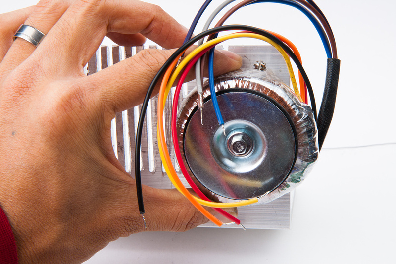
I decide to flip the toroid around to make wiring a bit more intuitive and dis-assembly easier if I need to service this later on.
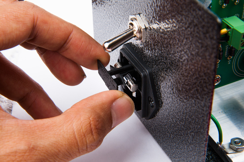
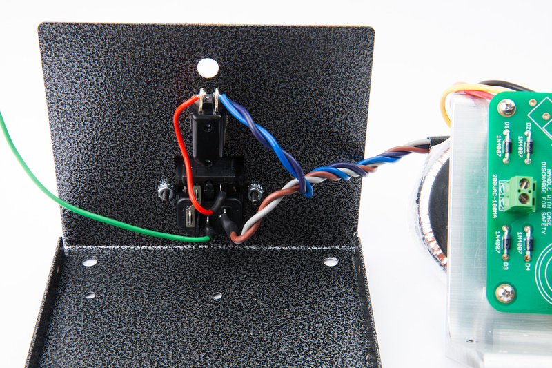
And, I wire in my power switch and fused IEC. Since I am in the US, I wire the primaries in parallel and the secondaries in series per my diagram in the point to point build.
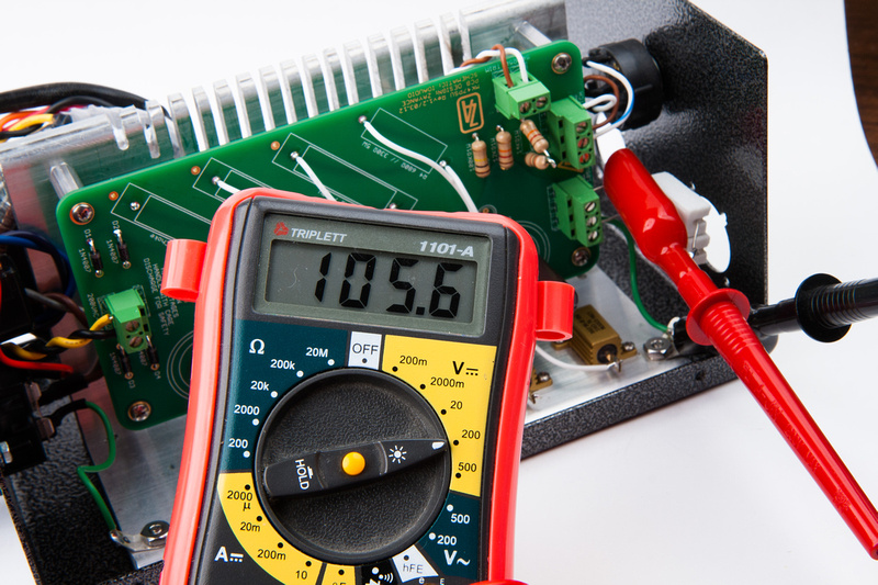
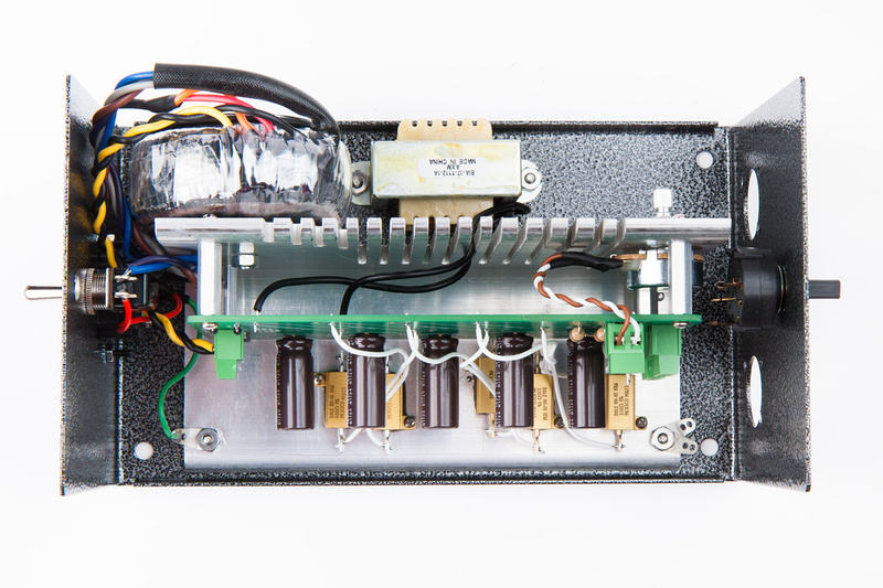
Secondaries are wired in, and I utilize 2 of my L-bracket mounting points for utility ground and for star ground near the locations where these attach to the IEC and the PCB.
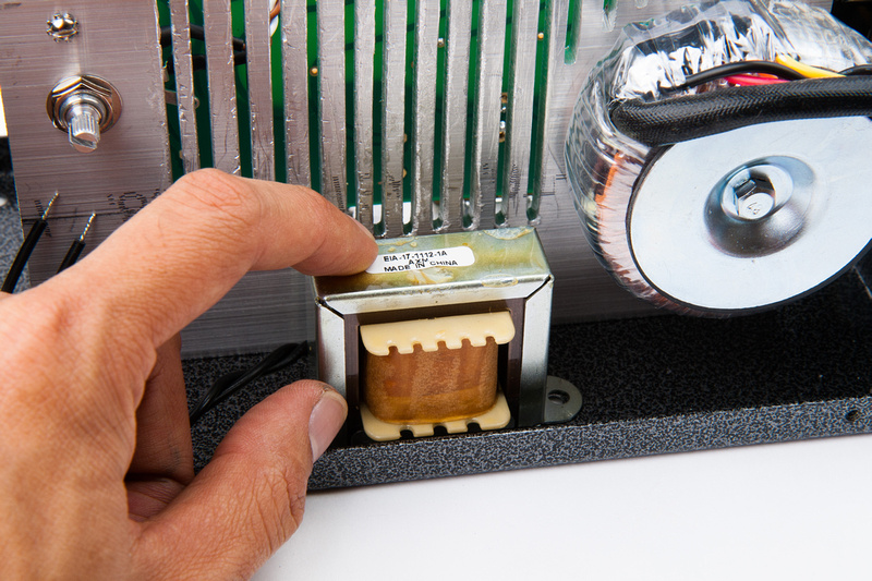
Next, I install the choke and wire that in.




![Soldering Iron Kit, 120W LED Digital Advanced Solder Iron Soldering Gun kit, 110V Welding Tools, Smart Temperature Control [356℉-932℉], Extra 5pcs Tips, Auto Sleep, Temp Calibration, Orange](https://m.media-amazon.com/images/I/51sFKu9SdeL._SL500_.jpg)


