newbie builds ioaudio MK47 microphone

GroupDIY Audio Forum

Help Support GroupDIY Audio Forum:

This site may earn a commission from merchant affiliate links, including eBay, Amazon, and others.
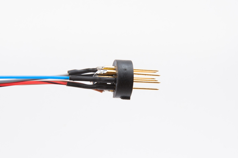
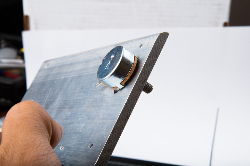
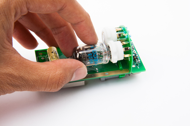
The ceramic tube sockets pins are very stiff when new, so I insert and remove a tube a few times to try and loosen up the sockets before soldering them onto the pcb.

p1158774028-4.jpg


p1158774278-4.jpg


p1158774550-4.jpg


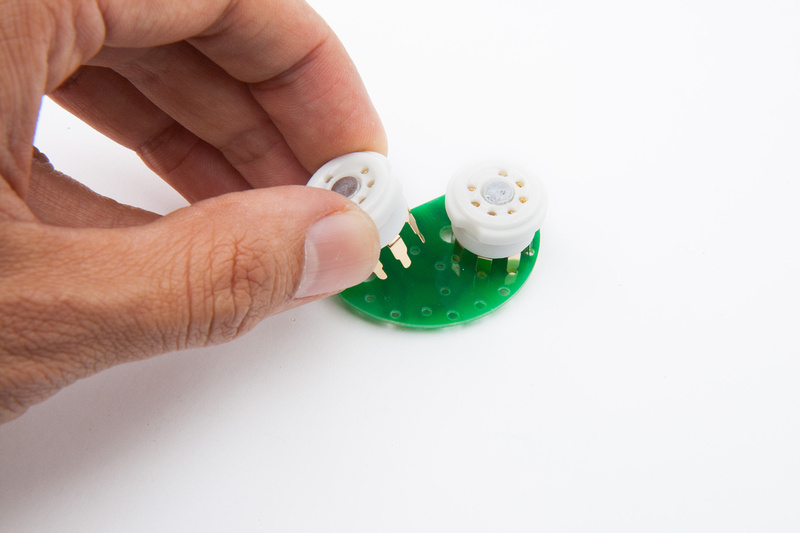
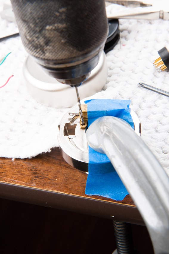
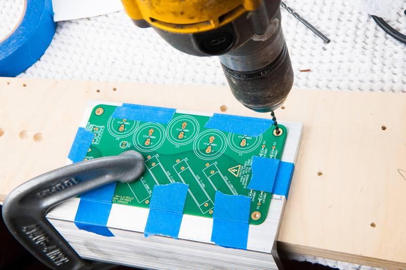
My tube pcb doesn't quite fit into the main pcb, so I round over the inside edges a little bit to make it drop in all the way.

p1158774858-4.jpg


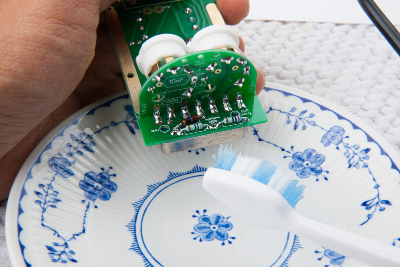
And, of course, I take the opportunity to scrub the tube socket PCB at this time with isopropyl alcohol to clean the flux residue off.

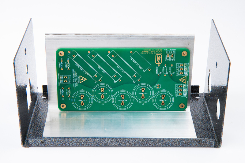
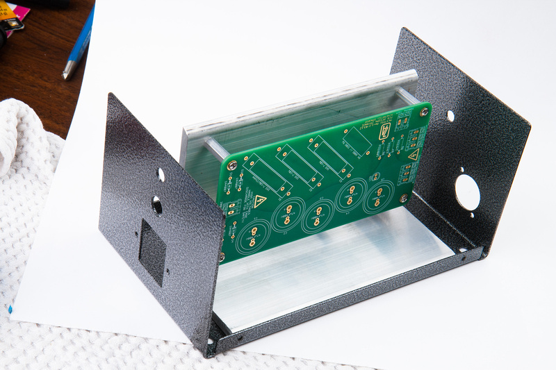
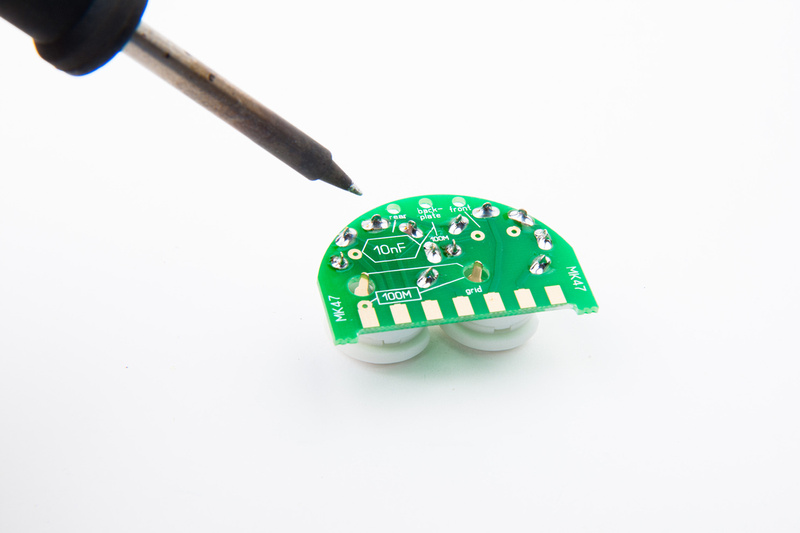
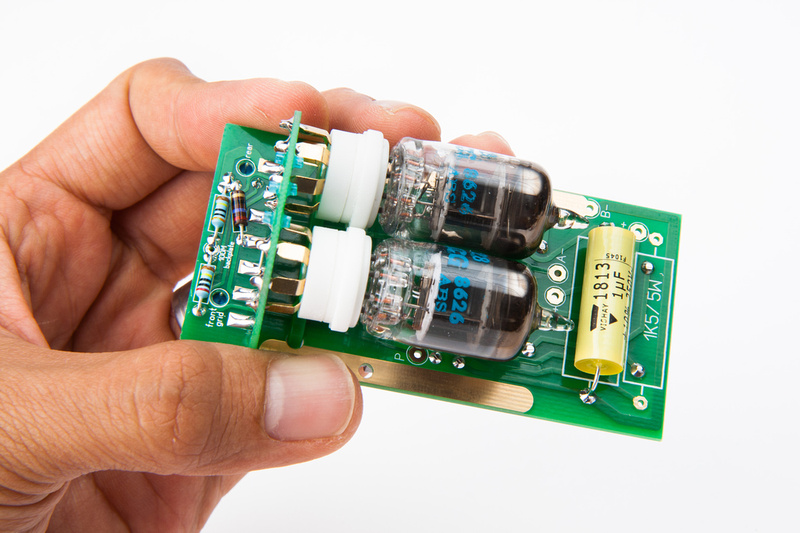
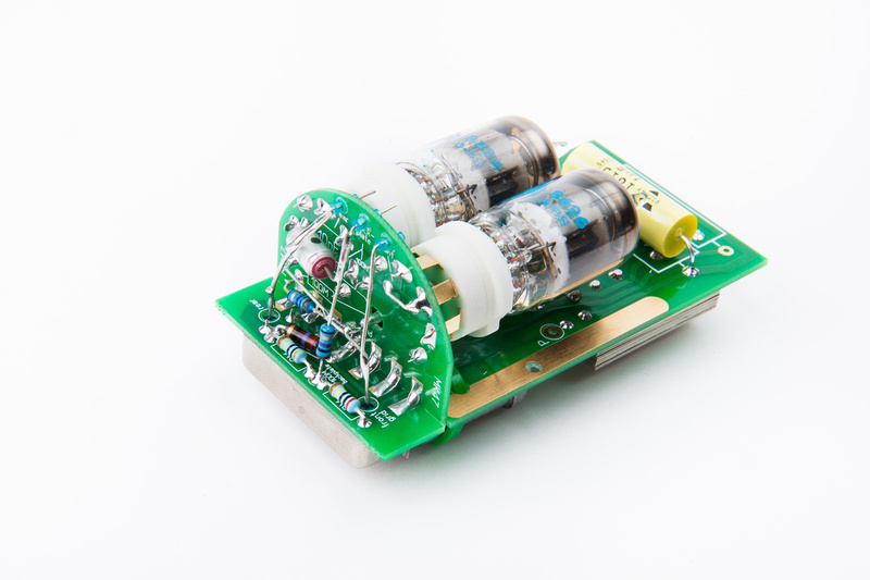
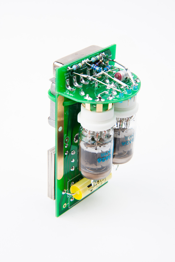
Next, I assemble the 2 pcb's.

p1158775004-4.jpg


p1158775404-4.jpg


On my kit, this position aligned the 2 PCBs perpendicular to each other, so I propped the board up and solder one joint.

p1158775716-4.jpg


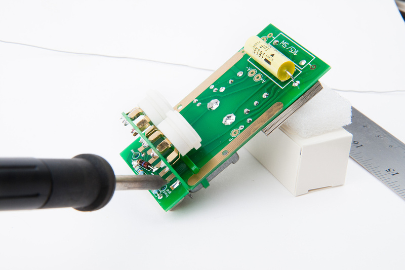
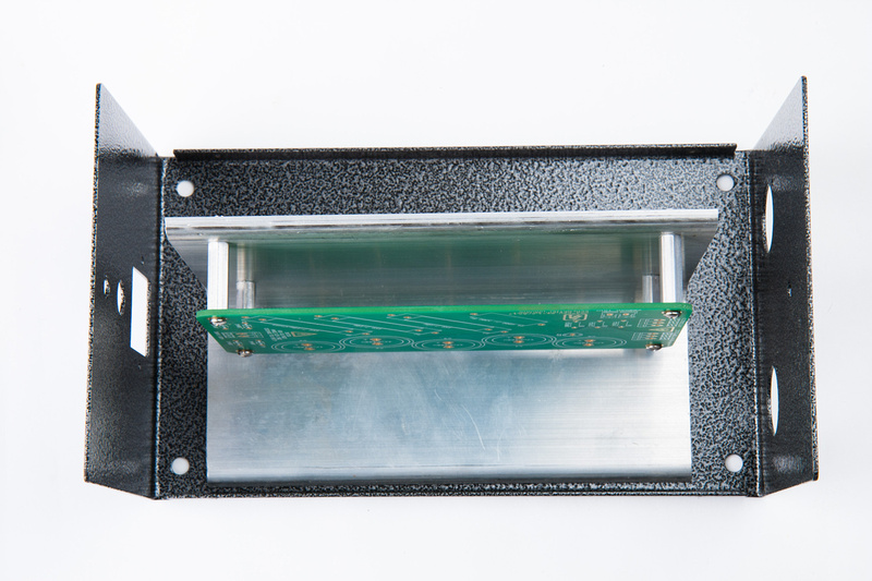
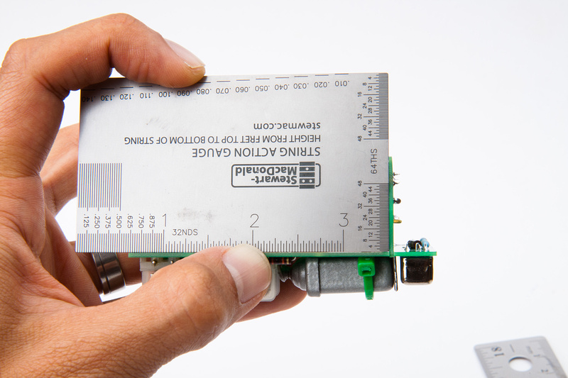
A square confirms that the alignment is almost perfect.

p1158776050-4.jpg


after soldering the remaining lugs, I clean the area with alcohol.

p1158776576-4.jpg


p1158777034-4.jpg


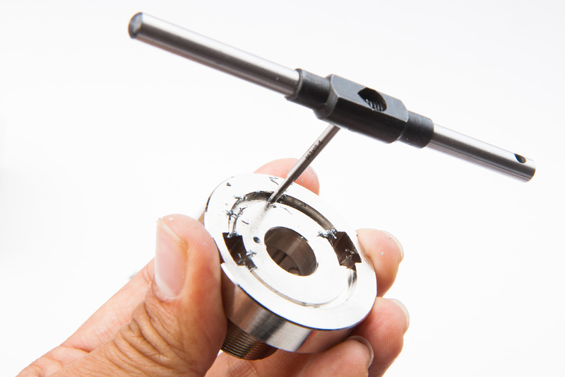
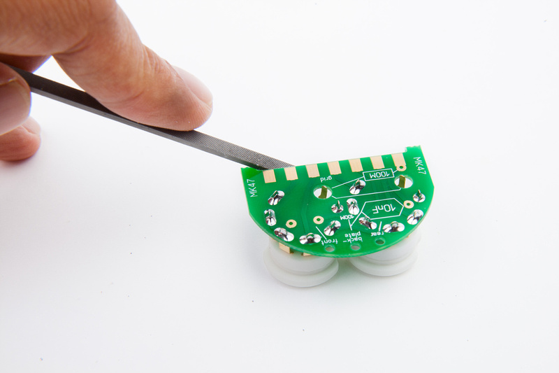
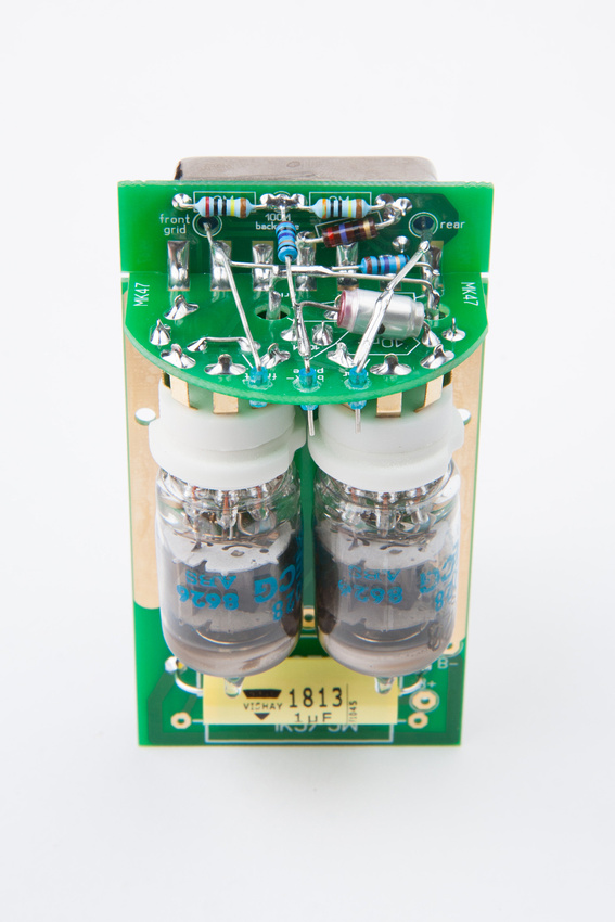
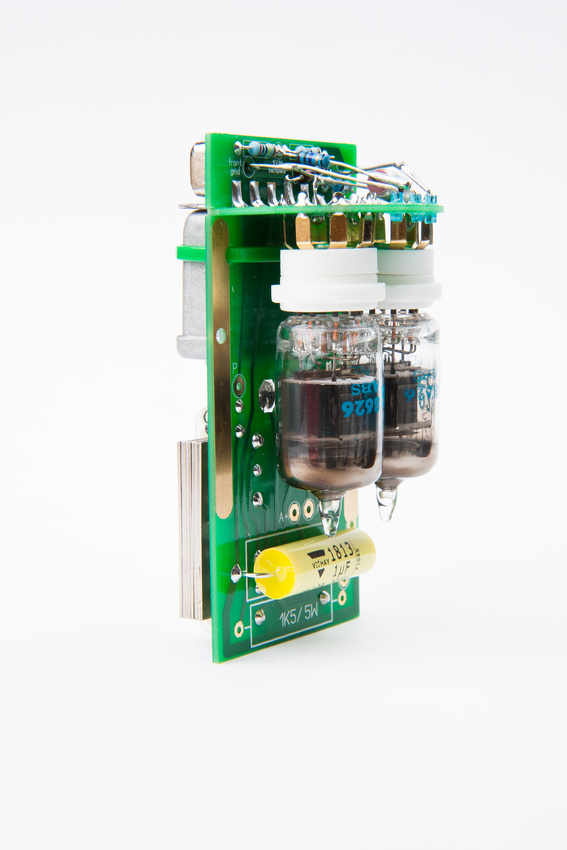
Next, I install the glass isolating tubes with some super glue.

p1158777338-4.jpg


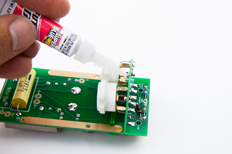
I discovered that it is much more precise to squirt a little puddle of super glue and dip a small component lead into it to dab the glue onto the glass tubes.  Do not get any of the glue on the inside of the tubes.

p1158777742-4.jpg


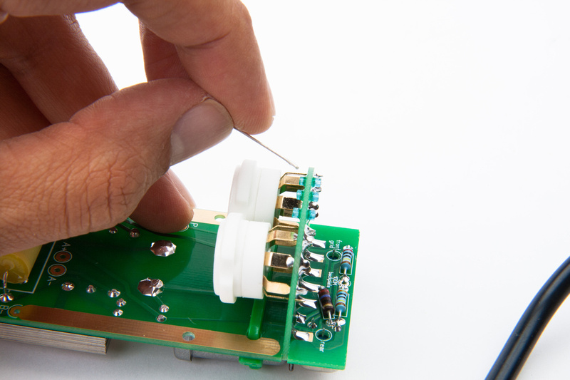
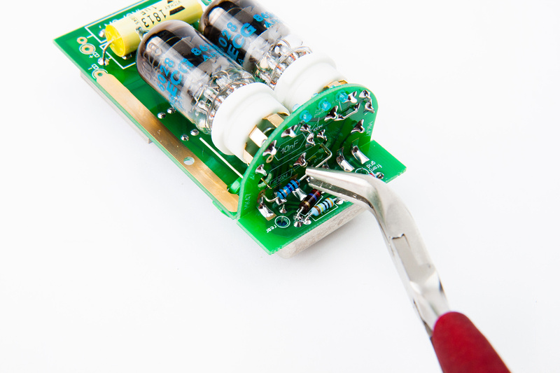
Next, I insert the tubes to push the socket pins into their fixed stationary positions.

p1158778456-4.jpg


p1158778782-4.jpg


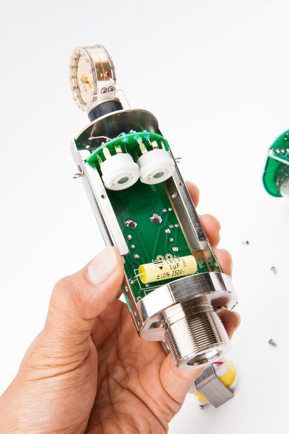
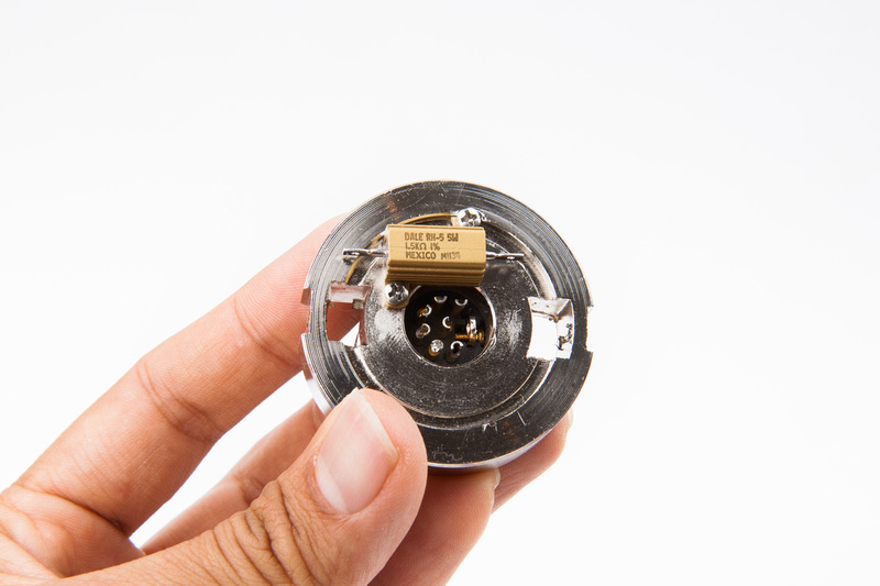
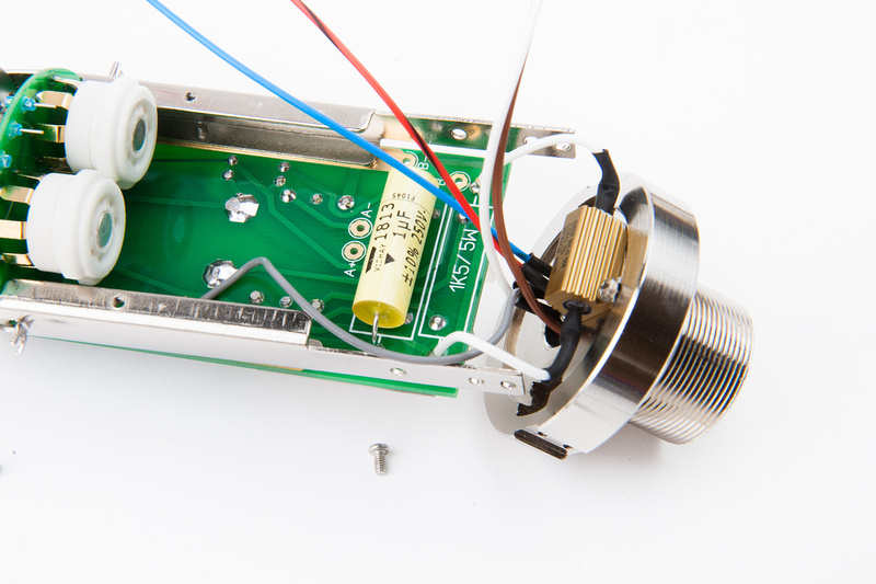
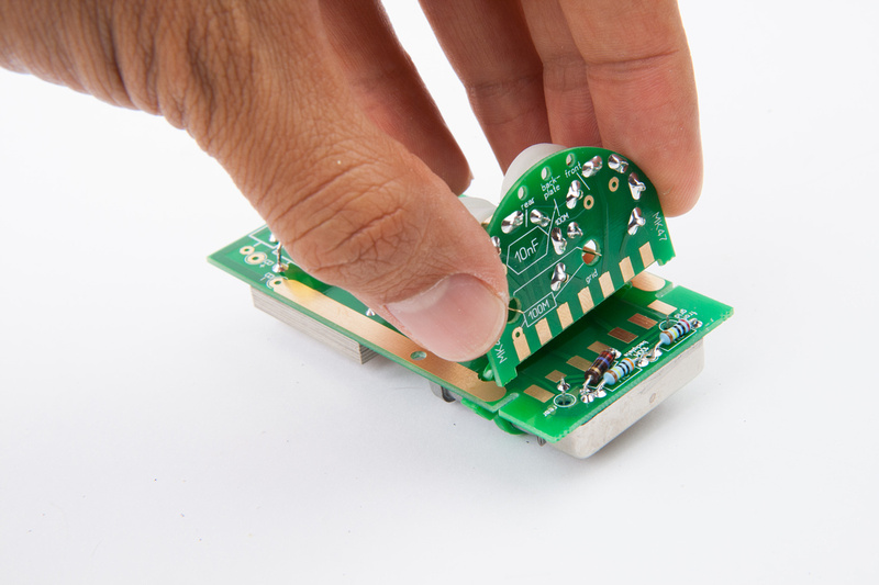
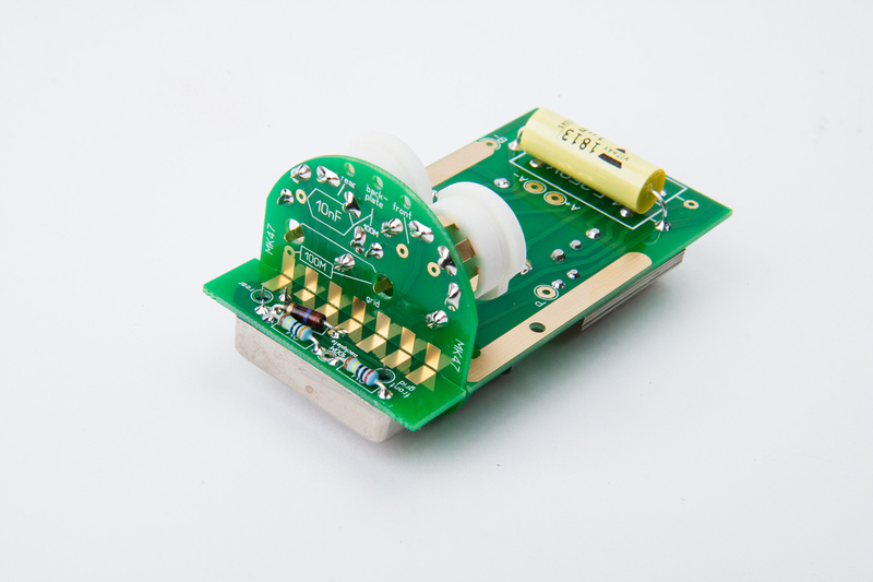
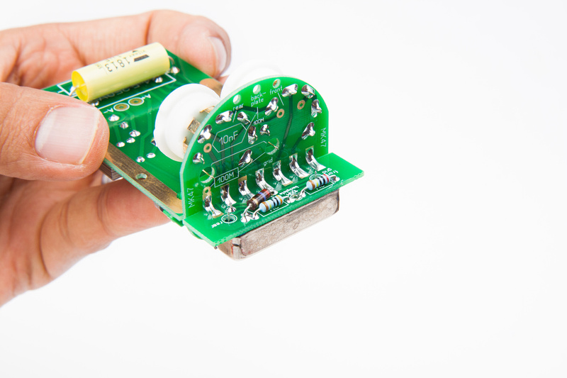
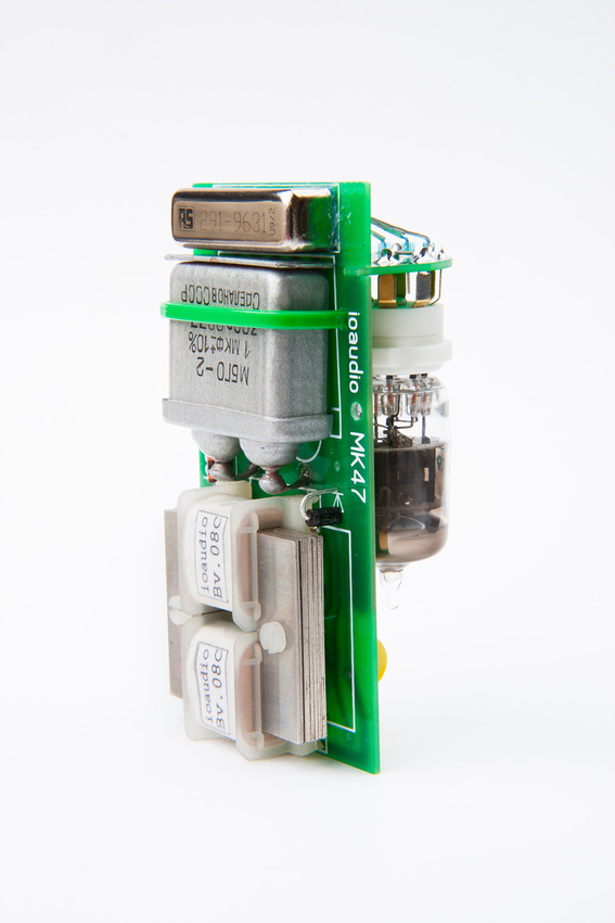
The, I begin assembling the floating high impedance portion of the microphone circuit starting with the 100M resistor.  A little bit of creative clamping was executed to make the solder joints.

p1158779308-4.jpg


p1158779676-4.jpg


p1158780310-4.jpg


p1158780916-4.jpg


p1158781514-4.jpg


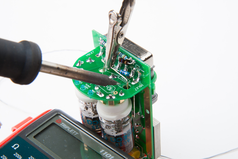
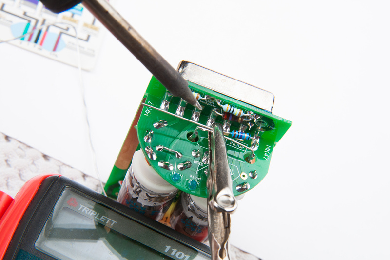
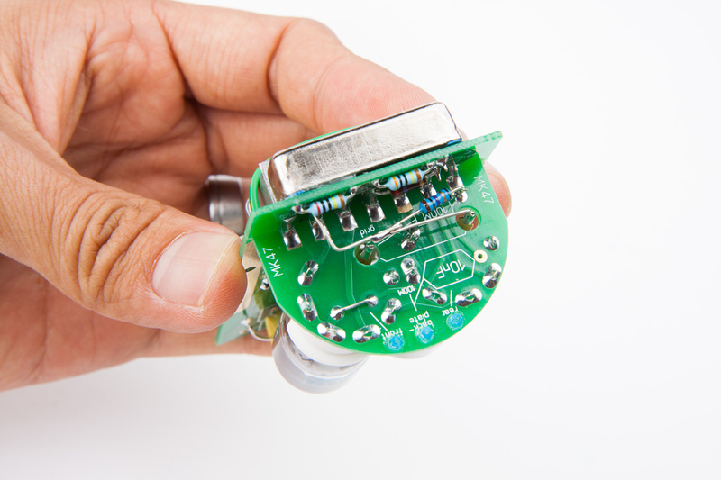
I ended up cleaning solder flux with alcohol as I went along making sure to avoid touching the capacitor with the alcohol.  I was not sure if the casing was deigned to withstand it.  I was not able to find a lead long enough to make the rear capsule lead connection in one shot, so I soldered 2 together.

p1158782136-4.jpg


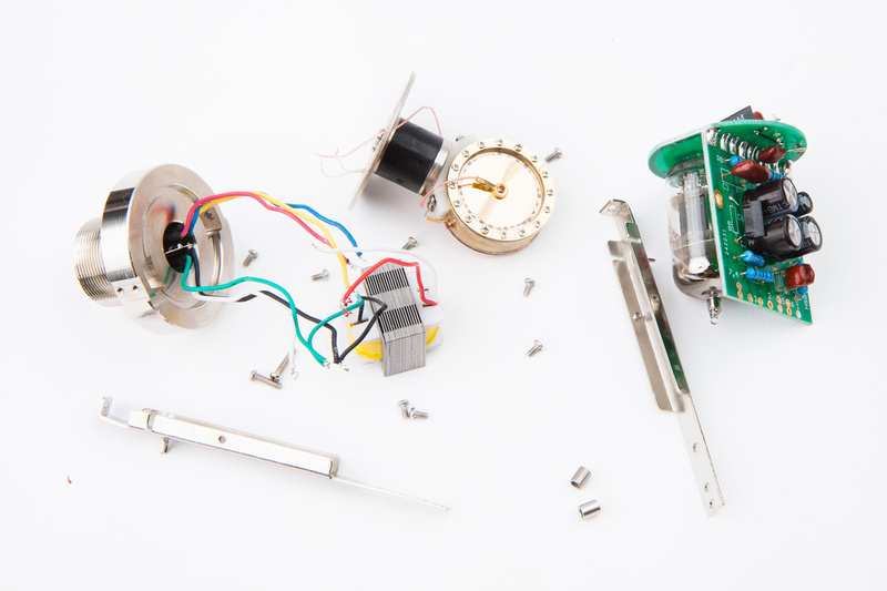
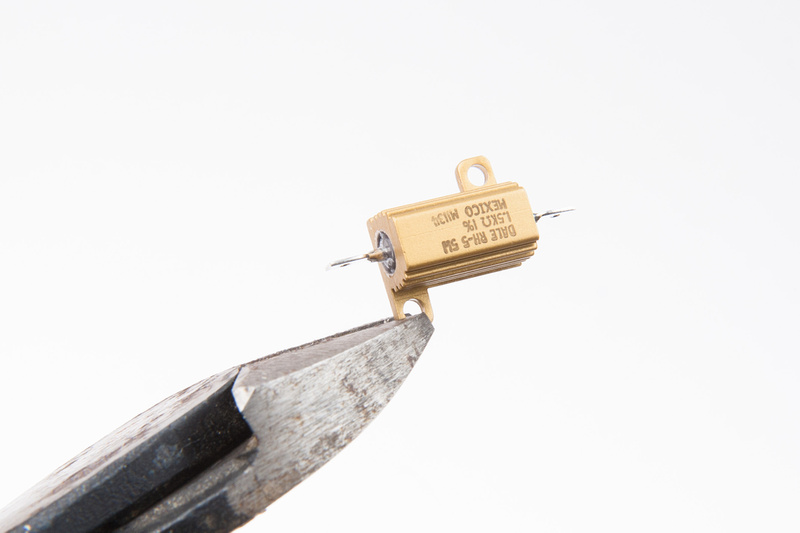
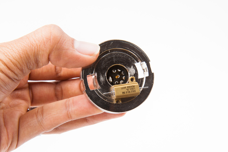
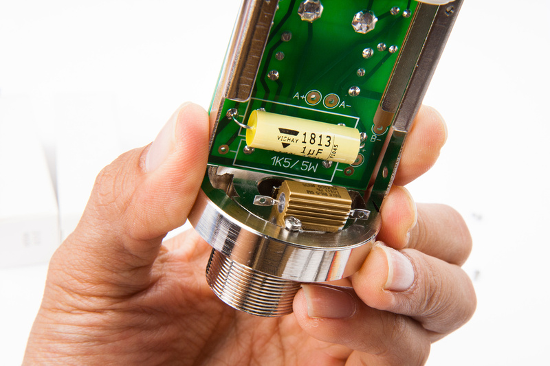
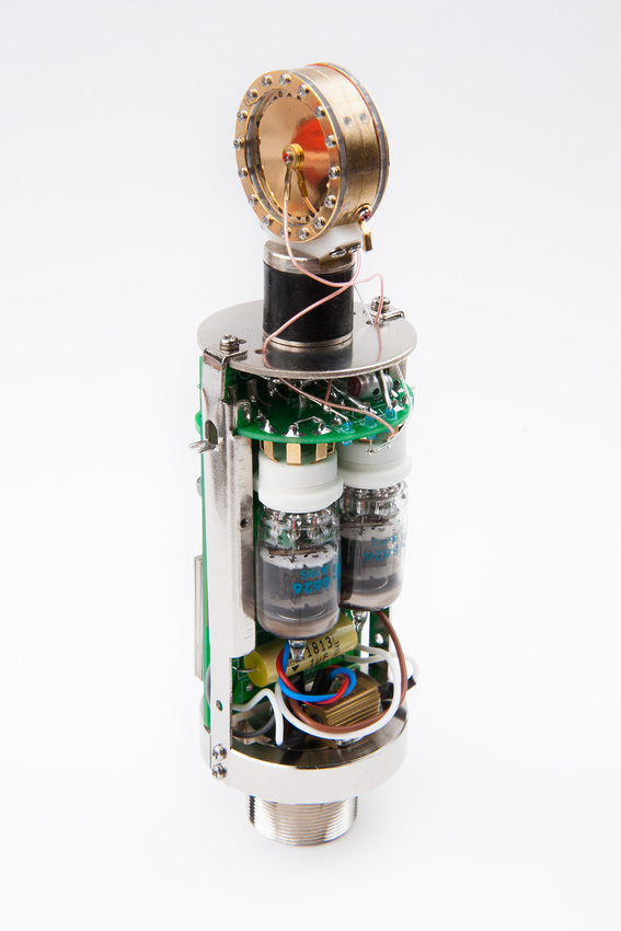
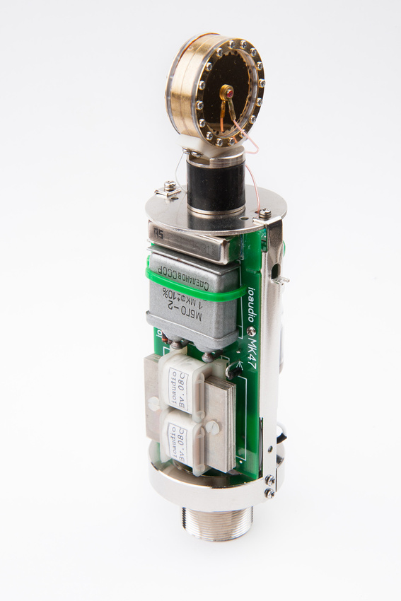
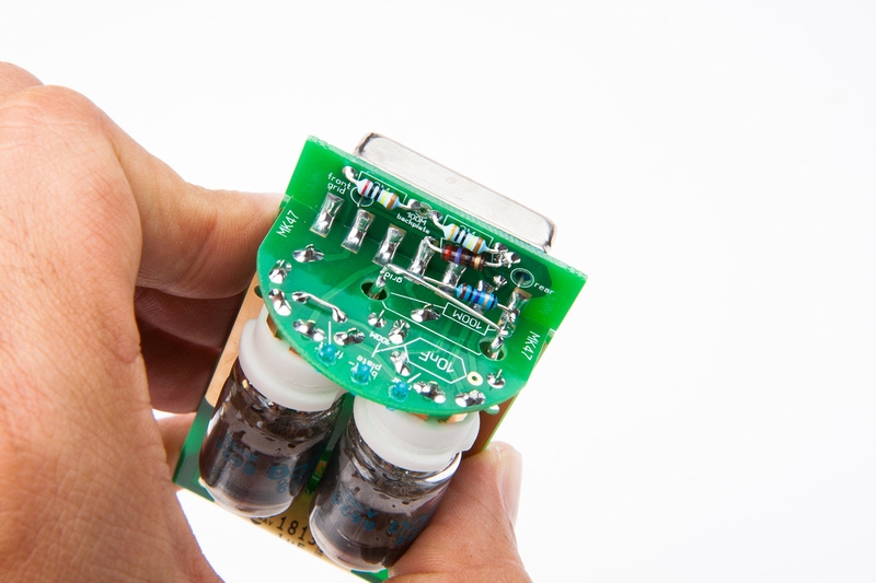
and, with the exception of the 1.5K heater resistor that needs to mount securely to the microphone body for thermal coupling, the internal circuit is completely assembled.

p1158782364-5.jpg


p1158783520-4.jpg


p1158784254-5.jpg


p1158784744-5.jpg


p1158785206-5.jpg


I must say, this is quite a fun build and the documentation on ioaudio's build thread made every step clear.  I'm looking forward to finishing a mic as soon as a GT-2B body arrives from the motherland and my Beesneez M7 capsules arrive from Australia.
 
Good things have arrived at the Chinese Labor Camp today!

p1163673820-4.jpg


p1163674124-4.jpg


p1163672054-4.jpg


I can see some light at the end of the tunnel here. . . it was a very, very expensive route I took to obtain a donor body for this build, but here it is  :eek:  
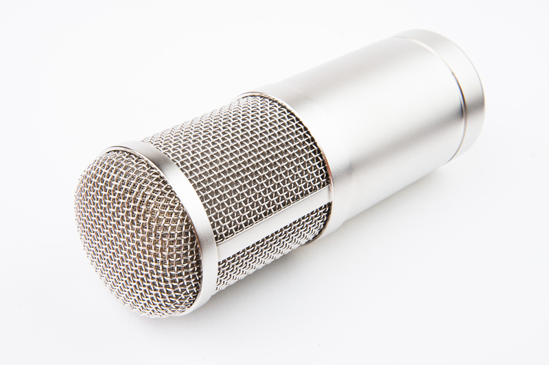
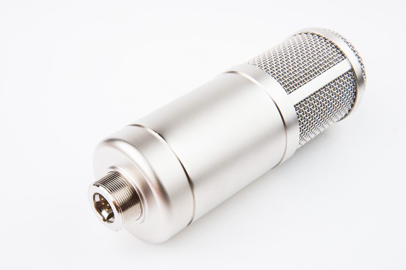
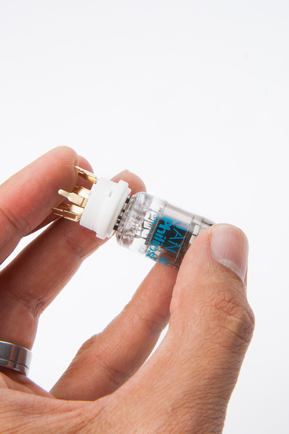
This is an unmarked Alctron GT-2B donor microphone.
 
Chunger,

You wired your Toroidal in Parallel on the input/primary side.  I thought it was supposed to be in series.  But your test results were right.  What made you choose parallel?

Thanks,
GH
 
Treelady said:
Chunger,

You wired your Toroidal in Parallel on the input/primary side.  I thought it was supposed to be in series.  But your test results were right.  What made you choose parallel?

Thanks,
GH

My understanding is this, and please double check because these high voltage sections can kill you or burn your house down if mucked up..  .

For 110V countries like the US, you should wire the 115VAC primaries of the toroid in parallel. . . for 220V wall power, you wire these primaries series.

What made the monkey decide to do this is the monkey has done it this way for the past 2 psu's he did (GDIY51x and JLM Powerstation) and it has worked out ok.
 
Hey Chunger,

Are you doing your builds in an all white scientific lab. The white backdrop and quality of your photos are amazing! I have never seen such a clean background.

Your thread builds are like a walking advertising for how products should look like.

I am not worthy  :'(
 
Out with the GT-2B stock internals.

p1191357784-4.jpg


And in with the mk47 kit.  As expected, a perfect fit in the donor body making mechanical assembly a breeze.

p1191358088-5.jpg


I deviate slightly from ioaudio's build instructions here by utilizing a chassis-mount type 1.5K resistor.  I have to modify it slightly to fit on the center flat portion of the microphone's base and clear the wires coming in from the 7 pin connector.

p1191358542-4.jpg


p1191358702-4.jpg


Once I've determined my resistor position, I drill and tap the 2 holes for mounting.

p1191359030-5.jpg


p1191360124-4.jpg


And, the resistor is mounted with M2 screws to match the threads on the rest of the donor microphone,

p1191360798-4.jpg


The fit and clearances look great.

p1191361146-4.jpg


Next, I install new wiring in my 7 pin connector.  I use some 22 and 20 awg silver plated teflon wire of various colors and refer to my wiring diagram for pinouts.  I'm not sure if it is correct, but I tie my audio ground (pin 4) to my ground (pin 7) at the connector because I do not see a separate audio ground lead for the microphone.  Just the (B-) terminal.  I figure it's a simple matter to cut that connection later if I have a noise problem for which I need to adjust my grounding scheme.

p1191361704-4.jpg


And, I begin to wire everything in.  A cleaner installation is possible if I shorten the wire leads, but I wanted to be able to pull the 7 pin insert out without disassembling the entire microphone if if I need to make small changes later.  So, I left some extra length on my wires.

p1191361790-4.jpg


The stock GT-2B capsule is connected temporarily for testing purposes. I do not have my Beesneez capsules yet and even if I did, I would have connected the stock capsule for function testing before risking an expensive capsule.

p1191362246-5.jpg


p1191362606-5.jpg


The microphone powered up beautifully on my PSU without any smoke.  The measured B+ voltage was 108.2V upon initial power-up.  I opened up my PSU and had to turn my trim pot all the way down, but I was able to get 105.1V which is just about spot-on.  I would certainly like to have some room to adjust, so increasing the value of one of the resistors in the PSU might be something to think about down the road, but for now, I'm happy with hitting my target voltage if only barely.

I have not had a chance to listen to the microphone yet because my little testing mixer is at the office for an audio gig, but my spectrum analyzer tells me I am getting good signal across frequencies.  For now, it appears I have some noise at ~100HZ, but I did not plug into one of the isolated ground circuits in the house yet and of course, I haven't actually put my ears on it.

If by chance I am getting noise, I may need to re-visit my grounding to see if something can be changed to minimize it.

For now, mk47 is alive.
 
Lookin good Chunger!
This body is a great candidate for the Amphenol 7 pin male end as well. It goes in with just a little boring and gives you the ability to have the mic cable screwed on. Not a necessity tho.

Sound tests with the K7 (when you get it) please!

Dave
 
Regarding capsules, I will report back with studio samples.  Due to another posting indicating the mk47 circuit may be "dark", I adjusted my capsule order with Beesneez and will be getting one M7 capsule and one K7 capsule.  Originally, I had ordered a pair of M7 capsules.

The K7 is reported to have a bit more on the top end and has been proven on mk47 where Beesneez M7 is relatively new.  I doubt they would release M7 as their flagship 47 type capsule with  a deficiency of any kind, but I figured I'd never know really unless i got my ears on both side by side.  What I do know is my particular studio setup often favors an airier source.

I have also located a good vintage U47 locally that I will also be able to bring in on testing day, so this should prove quite informative.  First thing is to get my micro-mixer back tonight and listen to the mic to verify function.

The noise was definitely not in the 60hz range.  I will plug it into clean power and listen again.  Hard to tell what's going on by looking at a spectrum analyzer without hearing anything.

I'm excited to finally have this up and running though.
 
Got my little mixer back and listened to the mic.  Everything is very dynamic and responsive across the frequency spectrum.  This is good.  I am hearing a hiss that sounds somewhat normal in audio equipment of all types.  It seem just slightly higher than I'm happy with.  There is a slight background crackle every once in a while.  From what I have read from others building mk47, I suspect the tubes need more than 5 minutes of run time before settling in.  I did however swap out tubes one at a time with 2 others and do not detect significant changes in the noise.

I put the microphone in front of some stereo speakers and will play music into them overnight and re-examine the situation after a few solid hours of break-in.

The microphone gets warm around the chassis-mounted 1.5K resistor . . . My version of the PSU runs completely cool to the touch  8)  The mic seems happy running upside down with the screw-on shock mount attached which gives more thermal mass and the inner wire frame acts nicely as a heat sink.
 
Time to make a cable. . . I'm using the Gotham GAC 7 cable and neutrik 7 pin connectors here.

p1220118482-4.jpg


p1220118608-4.jpg


For my studio and my pinout choices, I wire it:

1. red  (larger gauge wire)
2. blue (larger gauge wire)
3. yellow
4. gray
5. black
6. white
7. green and shield

p1220118712-4.jpg


Next, I move to my 2nd unit power supply which will be a PCB based build.  Choices, choices.  On top is Zayance's pcb that is currently available, and on the bottom is the pcb that Horvitz gave me for this build.

p1220118790-4.jpg


I also have a beautiful pre-drilled psu case from Dan at Collectivecases.com .  He is also in the white market.

p1220119056-4.jpg


To be quite honest, there are a few distinct advantages to the Horvitz pcb that would make it work better in this case.  First, because I'm using chassis mounted resistors, there is no need to eat up PCB space for them, and the Horvitz board is definitely more compact.  Also, the Zayance pcb does not have the test load resistor integrated into the PCB.  After a bit of thought, I figure as Zayance probably did when he penned the design, you only use the test resistor once.  Even then, you have to adjust again once the actual microphone is attached.

As for fit, here would have been the easy way for me to build my project.

p1220119524-4.jpg


Simply mount the resistors onto the bottom of the case, wire it up, and done.  Alternately, the Zayance PCB is too long for this arrangement.

p1220119820-4.jpg


I was very tempted just to build the Horvitz pcb as it would be much easier in my case, but it's not generally available, so I decide to demonstrate the build with available parts.

This will be my component arrangement in the case.

p1220120060-4.jpg


I've had this piece of aluminum L-bracket lying around that was originally for the GDIY 51x psu. . . before they came out with beautifully fitted case kit.

p1220120312-5.jpg


I fit my chop saw with a metal cutting blade and cut to length.

p1220120556-4.jpg


p1220120806-4.jpg


Next, using the PCB as a guide, I drill my mounting holes onto the L-bracket.

p1220121064-4.jpg


And, pull some standoffs, screws, and lock washers from my bin.

p1220121328-4.jpg


p1220121406-4.jpg


The PCB fits nicely.

p1220121442-4.jpg


p1220121806-4.jpg


The toroid will mount in this position.  I mark my drill location and make a hole for the toroid mounting bolt.

p1220122022-4.jpg


p1220122296-4.jpg


On the opposite side of the L-bracket, I drill to mount my voltage trimmer pot.  This pot has a stop pin that I could cut off, but instead i drill a 2nd capture hole so the potentiometer body will not rotate when I tighten it down.

p1220122648-4.jpg


p1220122816-4.jpg


p1220123058-4.jpg


p1220123222-4.jpg


Next, I decide to go a little crazy on the chop saw and do a little home-made heat sink with the main body of the L-bracket.  Never hurts to try and run cool.

p1220123466-4.jpg


It was quite difficulty trying to clean up the raised edges from the metal cutting bit, so I sortof scuffed up my L-bracket a lot.  So, it's not as pretty as I would like, but I think this will be quite functional.

p1220123798-4.jpg
 
Chunger strikes again! Why do i get the feeling your gonna have your own show on TV called...
"This old Gear with Chunger Villa" ;) Again, nice job C
 
This was supposed to be "the easy" version  :eek: . . . Why do I find myself grinding metal again?  New, compact PCB should be laid out for off-board resistor mounting IMO.

 
Nice.

But on a side note, thanks for using "the maybe more available PCB", but i'm not the official retailer of these, and i absolutly wouldn't mind
Horvitz having his out there for others who would like it small and tight, so for having Resistors off board, or save space etc...., I mean at first i made them just because
people were asking me the etching version i provided on the thread, and because i didn't had much time etching them, so i manufactured them
so if some were interested then easier for everybody, and we're all happy, i did about 20 first, and after there was some more interest etc...so..
The looks was like..."ok now that i'm back at it, let's have at least some fun and make it look nice...."

Anyway Why did you bother yourself with mine  ;D  :).
I think 10W a little off board is ok, and i guess all the people that bought these boards are ok with that as well. I could be wrong.

Anyway sorry about the trouble    :-\ :)
 
Hey Zayance,

I don't think anyone else wants to step up to the plate and make a batch of new PCB's  ;D  I like to try and help as many people as possible with these builds so I will default to readily available parts.

Horvitz made sample quantity order of these boards for his 2 personal builds probably like you did at first with your boards before the masses forced you to go into production.  When I started the project, there were none available, so it's great to have something for the folks who don't want to etch or do a point-to-point build.

I think it's all good fun and I don't mind making Aluminum dust all over my living room.  Good thing the wife is out of town for a few days  :eek:
 
chunger said:
Hey Zayance,

I don't think anyone else wants to step up to the plate and make a batch of new PCB's  ;D  I like to try and help as many people as possible with these builds so I will default to readily available parts.

Horvitz made sample quantity order of these boards for his 2 personal builds probably like you did at first with your boards before the masses forced you to go into production.  When I started the project, there were none available, so it's great to have something for the folks who don't want to etch or do a point-to-point build.

I think it's all good fun and I don't mind making Aluminum dust all over my living room.  Good thing the wife is out of town for a few days  :eek:

Zayance, your pcb is frickin killer! It's robust, i love the space as well as the look, very pro. I'm glad Chungers doing yours.

Peace
 
Back
Top