newbie builds ioaudio MK47 microphone

GroupDIY Audio Forum

Help Support GroupDIY Audio Forum:

This site may earn a commission from merchant affiliate links, including eBay, Amazon, and others.
Great!  Now you've done got the CFO involved. . . now she's going to find out about post #118 where I made aluminum dust all over the living room while she was out of town. . . Oh!  Did I type that out loud?
 
There is an important vocal session coming up in the studio, and I need to get the mk47 up and running in one way or another to throw into the mix, and at this point, I figure the Beesneez K7 and M7 capsules that I have been waiting on for several months now are probably indefinitely delayed.

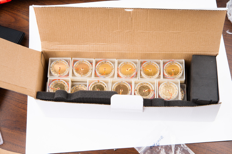
In the meantime, I have on hand a whole stack of high quality 35mm K67 type capsules that I have imported with the SYT-5 body kits.  While the K67 backplate capsule is not what most would consider "proper" for a U47 build, these particular capsules are generally connected to flat response CCDA/C12 type Chinese circuits and work quite well, so I figure some optimizations to smooth them out at least a little have been implemented.  Many industry insiders have informed me that this is in fact a VERY capable capsule.  While it may not yield a true U47 sound, my gut feeling is it will yield a high quality, useable sound to be considered as an option in the session.

p1423037730-4.jpg


Plus, the cost is almost negligible compared with a premium grade hand-made capsule, so there is no harm in throwing it into the mic and seeing what happens.  This way, at least I have the mic up and running and I can get some critical feedback from use in a production environment which after all, is the whole point, right?  :eek:

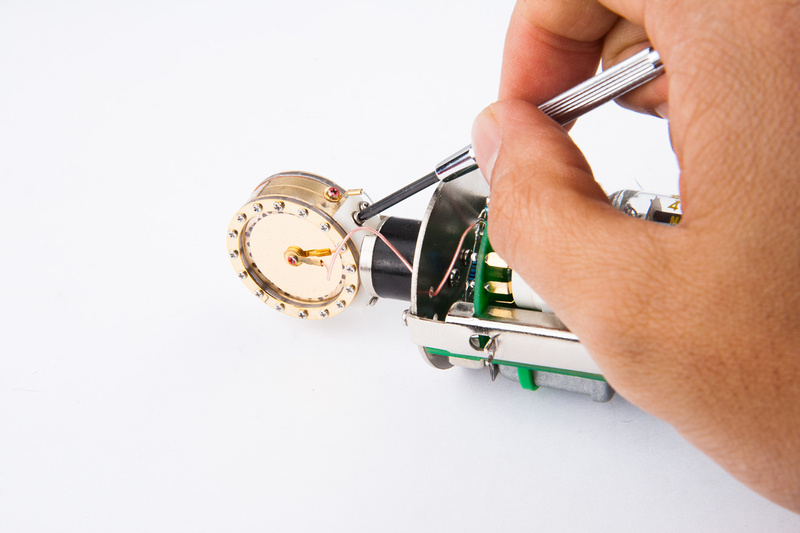
First, I remove the 32mm stock capsule and white saddle.

p1423037964-4.jpg


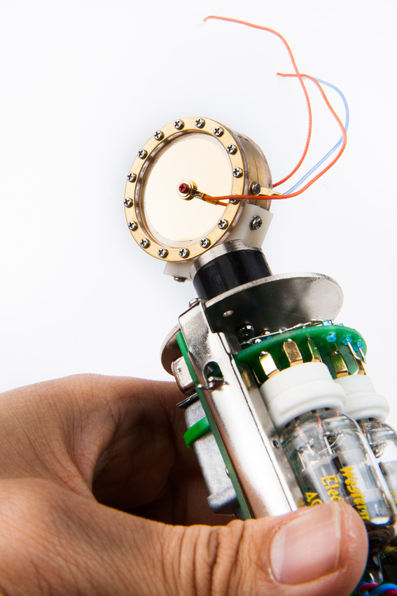
And install the 35mm capsule along with the a new saddle for the larger diameter backplates.

p1423038068-5.jpg


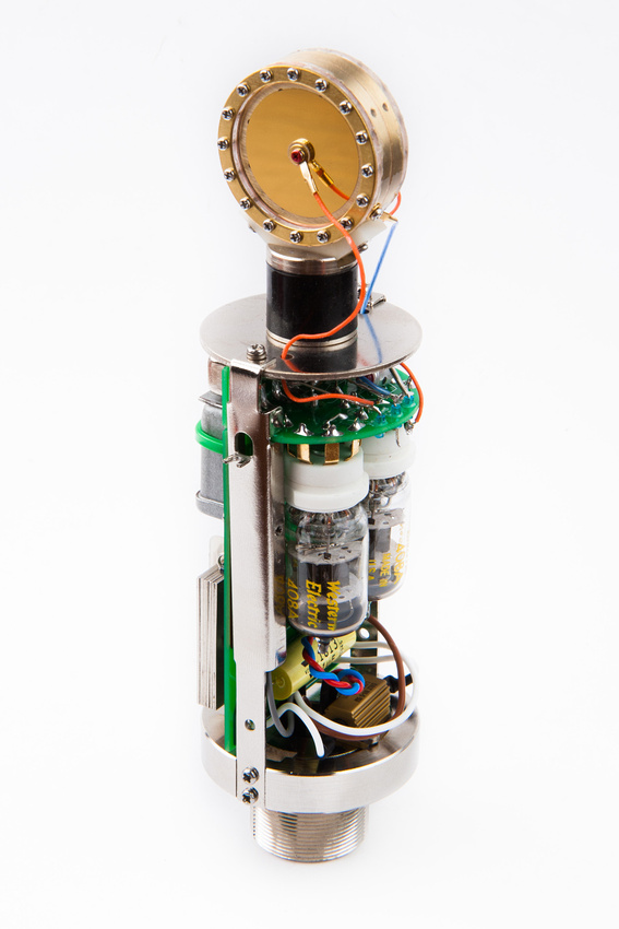
Notice also I have changed to Western Electric 408A tubes.  I found these to be a bit more open and articulate to my ear.

p1423038306-5.jpg


With the new 35mm capsule installed, I re-assemble the microphone and check my psu voltages.  I notice a ~5V drop on both power supplies upon installation of the new capsule so I trim the PSU's back to 105V and take a quick listen.  My monitoring system is not very good at my house, but my initial impression is the new capsule is much smoother than the stock 32mm GT-2B capsule with good bass authority and nice proximity effect.  I will delivery the microphone in this state to the studio for the vocal session and see how it pans out.  I believe the mic in this configuration should be quite useable.
 
micaddict said:
I figure the Beesneez K7 and M7 capsules that I have been waiting on for several months now are probably indefinitely delayed.

Why would you assume that?

My ~monthly pings for a brief status update that used to yield a quick reply have gone un-responded to for a while now.  I know the family is in a very tough situation right now with important medical issues, so I figure there are many possible reasons capsule production has been delayed.  I am sure my order will be processed in the order received, but it seems after an initial batch of shipments, things have gone a bit silent on the business side of Beesneez.  I will simply wait for Ben to re-surface when he has time to return to capsule production.  Under better circumstances, I read that previous group buys also had very long lead times.  I'm assuming with the recent spike in DIY microphone interest and favorable discounts offered, many orders were placed.

A few folks who are well ahead of me in the queue also have not heard back, so I figure it is safe to assume I will probably not be seeing capsules any time soon.  I'll just keep my eyes on the pertinent threads for updates and carry on here with a low-cost patch to put the microphone in the field.
 
Indefinitely suggests we won't get what we paid for. I personally don't believe that and going by your later reply it seems you still have hope, too.  ;)

Turnaround time with builders like Ben can be long, regardless. E.g. three months for Tim Campbell's capsule is quite normal. If we add to that the huge medical trouble the Sneesby family has been facing (along with moving capsule manufacturing -which would include their CNC equipment etc., most likely- to the US) we should probably count on a couple months more. But from what I know, Ben is a stand up guy (not to mention Veronica; well OK, she's not a guy) and he will deliver.

BTW, I did have e-mail contact with Veronica, just yesterday (after inquiring about my K6). It seems she's trying to catch up on all the shop e-mails (her response was via her own e-mail address). As soon as I have some (more) useful info, I'll see if I can share that or better yet, direct Ben/Veronica to this forum.
No affiliation BTW.


Henk
 
in·def·i·nite  [in-def-uh-nit] 

adjective
1. not definite; without fixed or specified limit; unlimited: an indefinite number.
2. not clearly defined or determined; not precise or exact: an indefinite boundary; an indefinite date in the future.

;D

I mean to say I do not know when my capsules will arrive. . .
 
OK, you win.

To my "defense" I'll say that I wrote "suggests", not "means". But "may suggest" might have have been better.  :)

Anyway, enough semantics. It seems we agree there's hope.
 
Hey Fella's,

I hope Chunger doesn't mind, but i thought this would be a good place to post a picture of a project i did. I know a lot of guys used Chungs mics as donors for the MK47, so here is my idea of a good use for the donor PSU case for the Alctron.

Stereo Bo Hansen active DI anyone?
 

Attachments

  • big bo hansen.jpg
    big bo hansen.jpg
    686.5 KB · Views: 107
HI Fella's

Here's my latest conquest, thanks to Chung, without his awesome threads, i wouldn't have gotten so into all of this great fun!

It started as a military ammunition case, I used as many parts from the donor Alctron PSU as possible. Not sure if the polar switch will work yet, i nipped out all the contacts but 2 for cardoid/omni. I went a little overboard with the shielding :eek:

enjoy
 

Attachments

  • amo MK47 case 2.JPG
    amo MK47 case 2.JPG
    81.4 KB · Views: 69
So Thank You Chunger and Thank You Max and Thank You Zayance. The build she is done. Sounds great too!

So far Cathedral Pipes Capsule and Shock Mount, Equinox Body, Binder 691 Connectors (on mics side) throughout and Hammond Case. Obviously Max's kit and Zayance's PSU PCB both of which qualify as high art in my book.

I had to pay strict attention to this one as the build was not straight ahead. For all who follow, you must read both Max's and Chungers build threads if you are going to get this right the first time. There is a lot of important information throughout.  Also note the differences between Max's PSU Schematic and Chungers Layout and the reasons why. I also would recommend that you get yourself a good selection of colored wires as you really need to delineate between things when doing the hook-up. A minor note if you use Zayance's PCB you need radial filter caps not axial.

I have not decided on a knob yet or a pilot light. My one nod to visual arts. I also may see how a Thiersch M7 sounds in this as I am working on another UM47 Clone.

Again Thanks Too all who made this possible. A very rewarding build!


Attachments

  • Untitled-1.jpg
    Untitled-1.jpg
    72.9 KB · Views: 284
Hi Pip,

Congrats to your build!Very nice psu layout,I like the mounts on the L-bracket.
I have a Thiersch M7 in mine and must say I like it very much,therefore recommended ;)

Best,

Udo.
 
kante1603 said:
Hi Pip,

Congrats to your build!Very nice psu layout,I like the mounts on the L-bracket.
I have a Thiersch M7 in mine and must say I like it very much,therefore recommended ;)

Best,

Udo.

+1 on the Thiersch M7, nothing but quality
 
Okay....almost finished this build but...cannot figure out if there is supposed to be an internal switch for testing when one uses Zayance's pcb. I have been through the entire build section as well as this one. I only see the pattern selector switch and the trim pot for the 105V out.
Is the switch only there if the resistors for testing are built into the board (as shown on page 3)?
Thanks
Mac
 

Latest posts

Back
Top