NWDR U17a tube diode bridge compressor on Eurocard

GroupDIY Audio Forum

Help Support GroupDIY Audio Forum:

This site may earn a commission from merchant affiliate links, including eBay, Amazon, and others.

E7b9b13

Member
Joined
Jul 29, 2021
Messages
12
Location
Germany
Hello to all,
after finding this compressor in the Braunbuch, i have been wanting to build a version of it for months, and since i currently have no music to be recorded, I decided it might be a good time to finally get some of my ideas out of my head and into the studio.
This compressor is quite a simple circuit, with only two ECC81 double triodes as active amplifying parts, one for the make-up gain after the diode-bridge, and the other in the side-chain.
The diodes in the attenuator bridge are DS62 germanium diodes, which are equivalent to OA95 according to a equivalence chart i found online.

I think it would be really cool to fit this compressor onto a single 10x16cm Eurocard PCB, wich I think should be possible if the sidechain would be replaced by a solid state sidechain, which would get rid of a plate choke (the same as in the V72), a tube and the sidechain output transformer, also saving quite some money.
The power supply obviously has to be realized externally.

With that, it should not be to hard to get this thing on such a small PCB, even though there is still going to be quite some Iron on this thing: input transformer, interstage transformer, output transformer and plate choke.


Now i will have to figure out a way of building a solid state sidechain, and my first thought went to an op-amp for amplification followed by a drv134pa balanced line driver, since I have two of those laying around, and the output of the sidechain seems to be very similar to a line output stage.
The timing circuit after the sidechain output transformer could be used like it is, and maybe upgraded with a couple of various timing settings.

I would be very thankfull to hear your criticism and suggestions about this project, especially regarding the sidechain.

Best regards

Milan
 
Last edited:
I hope I will be able to do a scan of the full description some time over the next days, but i think for now, this should work
 
Looking at the compression curve, I think it would be easy to shift it around by altering the amplification of the sidechain. It would probably be even better to apply a positive dc bias controlled by a pot on the input of the sidechain rectifier as a threshold, so then the sidechain amplification control would become the ratio control if I am thinking correctly.
 
It would probably be even better to apply a positive dc bias controlled by a pot on the input of the sidechain rectifier as a threshold
The polarity of the bias obviously tepends on the way i attach the rectifier to the drv134pa output, in case anyone is confused (I was for a short moment after reading my post and looking at the schematic)
 
That might be most shallow compression curve I've ever seen. I don't gain a lot of insight from what google translate gives me from the manual. It reminds me of a bare bones NBC/RCA utility vari-mu piece used for additional control to lessen manual fading needs.
 
The first paragraph of the description would translate to something like this:

Application
The dynamic-compressor U17a is mainly meant to be used in transmitters, of which the low signal levels need to be amplified in order to increase the signal to noise ratio. The compression is realized with an input-level-dependent regulation of amplification and causes the dynamic range to be narrowed. The amplification is 11dB at an Input level of ≤-40dB and goes down to 0dB at +6dB. Therefore, when driven correctly, the allowed maximum level is not exceeded. The regulation is done in such a way, that no disruptive distortion or noise occurs.

So yeah, it is meant to be a very restrained compressor, but I imagine that could be changed with a threshold and ratio control like I described in an earlier post. But I do yet have to order some parts like the diodes to build a test circuit to see how well this works.
 
Last edited:
Theres a lot of transformers and chokes in there that will be near impossible to get , If you found the specs you might stand a chance of finding near equivalents , it will still cost many hundreds of euros in iron cored components , if it ends up not working you've dug a big hole for yourself .

What about the Rhode-schwartz U23 ? I think a few people might have tried it

https://groupdiy.com/threads/rohde-und-schwarz-begrenzungsverstärker-abr-u23.75426/page-13
https://floatingpoint.audio/gb/compressors/u23m
 
Ok, this thing is feed-forward rather than feedback, if I'm seeing it correctly. I might be doing it wrong, looks like 1.3:1 ratio. That would match what it looks like. Agreed you could change the side chain for more, though, there are plenty of similar concepts that are already there. The basic amp looks a lot like the Collins 26C and 26W for instance, though they are feedback compressors. Nothing wrong with chasing an experiment to it's end though, answer the curiosity. No reason it can't be a SS side chain along the lines of your thinking.
 
Theres a lot of transformers and chokes in there that will be near impossible to get , If you found the specs you might stand a chance of finding near equivalents , it will still cost many hundreds of euros in iron cored components , if it ends up not working you've dug a big hole for yourself .

I do realize that the iron will likely be by far the biggest issue in this build, but i think it is manageable. The Choke is the same as the one used in the V72, and there is some information about it on this forum. For the Input transformer, it should not be too hard to find something fitting, as it is a 1:1+1 ratio. The output transformer is the same as the one in the V72, too. Untill I have decided what exactly to use for it, I will see if I can use an Edcor 15k:600 with both halves of the secondary in parallel. As for the interstage transformer with a ratio of 1:7,04, I will try to wind one myself, as I wanted to learn how to wind transformers anyways. Untill I have wound that transformer, I will use an Edcor 150:10K for testing. 150:10K would translate to about 1:8,16, which is not exactly right, but I think it is close enough for some tests. The plate choke and transformer for the sidechain will be ommitted as I said earlier, since the sidechain is going to be solid state.
 
This would make a good mixbus compressor, yes it is feed-forward, like the U73b.

What does the abbreviation "abgl" stand for?

I think a Hammond 156C would do a reasonable job for the chokes.
The release timing looks to be between 6-9 mS, if abgl means variable.

best
DaveP
 
I can make a few observations about this circuit:-
The germanium diodes used for the bridge needed balancing to make sure that they operated in their linear regions (they were inconsistent). The Neve 2254 used a quad diode package called a HBX31 and did not therefore need balancing.

The gain of the output amp is x 79, but the gain of the sidechain amp is x 32, so there is scope to tailor the gain to suit other transformers if required. In both amps the output tube runs at about 4.5mA and the input tube has 1.6-1.7mA of dc from the output tube to the input cathode. The gain variation is controlled by the amount of feedback between the cathodes and their working points. It is a very elegant amp.

The DCR of the chokes is about 24k in my calculation (CJ could confirm the DCR of the V72 choke). Chokes were very common in the 50's but a resistor could also do the job if the gain was increased to compensate, this could change the sound, but so will more modern components, the Neve 2254 did not disappoint despite the lack of chokes and subbing transistors for tubes.

The source resistance of the sidechain works out at 4k. (1mS/250nF =4000. This would have to be maintained for any other sidechain.

The interstage TX (CTV69/1) could be subbed by a LTP tube feeding a push pull output stage.

Hope that's helpful.

best
DaveP
 
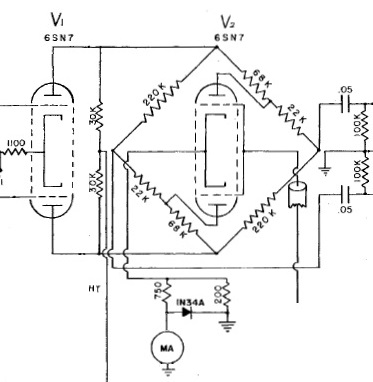
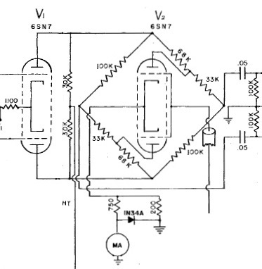
There are some interesting alternatives for the Diode Bridge:-

This is an extract from a resistance bridge compressor, it uses a positive CV on the control tube to reduce the resistance.

I have experimented with different resistor values to obtain this circuit which works with a negative CV on the control tube.

I found stability problems with positive going CV's, but not with negative, that's why I developed it.
best
DaveP
 
I have been delving into the specs of the three compressors, U17a, U23 &U73.

The U17a is a diode bridge compressor from Nov 1954, the other two are vari-mu's from Sept 1955 and May 1964 respectively.

The U17a states both hum and noise as 250uV on a +6dB output level. This works out at -75.8dB

The U23 gives 500uV noise on +6dB -69.8dB or -75.8dB on +12dB output.

The U73 just states the hum as -74dB and the noise as -80dB when limiting or Hum -64dB and Noise as -70dB when compressing.

What struck me was that not much improvement had been made in 10 years, or alternatively, that the U17a was actually a good low noise compressor.

You could also say that the miniaturisation process kept the hum and noise the same!

best
DaveP
 
Back
Top