NWDR U17a tube diode bridge compressor on Eurocard

GroupDIY Audio Forum

Help Support GroupDIY Audio Forum:

This site may earn a commission from merchant affiliate links, including eBay, Amazon, and others.
I translated the operating Instructions, attached:-

It looks like the germanium diodes in the 50's were not very reliable and that they needed to be changed. I guess this is the reason that the later U23 and U73 went over to vari-mu designs.
best
DaveP
 

Attachments

  • U17a Operating Instructions.pdf
    253.7 KB
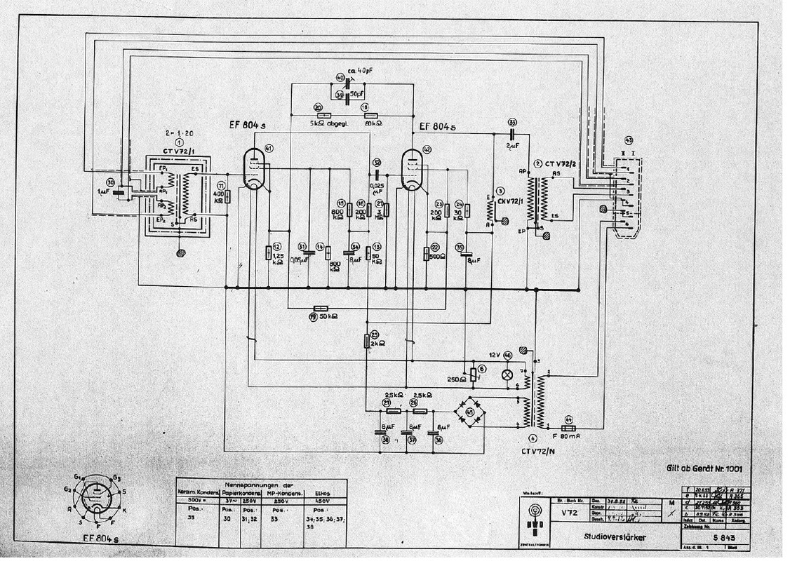
Looking at the schematic in detail, it is in fact a slightly modified V72 circuit, using ECC81's instead of EF804's

These are the common points:-
~100k of DC NFB.
Rk1 is 1.25k
50k of inter-cathode DC NFB
V72 Choke loaded output tube.
2uF output Cap.
V72 type OPT.
The date of the V72 drawing is August 1952, just 2 years before the U17a was drawn.

This means that choke loading would be absolutely necessary to provide enough drive for the large amount of DC lost through the 100k NFB resistor.
Having said that, it would be possible to insert a 2uF cap after the 100k NFB resistor, as was done in the later V77 (1959).
best
DaveP
 

Latest posts

Back
Top