Official G7 microphone help thread

GroupDIY Audio Forum

Help Support GroupDIY Audio Forum:

This site may earn a commission from merchant affiliate links, including eBay, Amazon, and others.
Upon measuring voltages without the capsule connected I think I've got a problem.

G7%2BVoltages.jpg


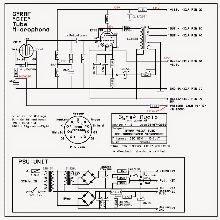
As you can see the voltages of the capsule's backplate and the polarisation voltage are not exactly the same, at the voltage divider I'm reading +/-64V and at the top of 33M resistor 72.8V.

I've found a workaround by someone one the WWW but I don't know if it's the right solution.

G7_Fix.jpg


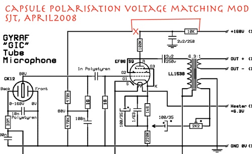
Should I just try it out?
Sorry for the total noobness ::)

I would love to hear your insights.

Cheers
Moshe
 
OK

So I just went ahead and did the above mod.

Now I have 71V on top of 1G Ohm resistor and 72V (in cardioid polarity) polarisation voltage.
In fig 8 polarity I get 144V so still no perfect match but better.

I don't know if it is really important to get the voltages to exactly be the same.
Someone experienced the same problem?

Cheers

Moshe
 
Not a real problem - only slight differences in actual pickup pattern. Somewhat less than standard dual-side capsule sensitivity differences, methinks..

Jakob E.
 
My capsules should NEVER be polarized higher than 60/120v. A lower polarization voltage will also improve the sound of the mic by allowing freer movement of the membrane.
 
Yes, it will change plate voltage too - but with no ill side effects to the audio, as long as you don't go below some 105V or so in the powersupply (measured with mic attached and fully heated)

Jakob E.
 
Thanks Tim and Jakob for the clarification.

There was a lot of confusion at least for me regarding the right polarisation voltage.

So just to summarize:

1. All the popular capsules (M7 style, C12 style etc.) should be polarized with 60V/120V.
2. There is some benefit for the plate voltage to be set at 160v.
3. Plate voltage can be as low as 105V

Hope I got it right now.

Cheers
Moshe
 
Hello Guys,

I just finished my first G7 mic with CT12 capsule. I have moded the circuit as seen on the picture, to get the right voltage for the capsule. Now I read 60V on the backplate, 61,5V on card., 123V on fig.8 and 0V on omni. Measured at mic XLR connector. Cardioid pattern seems to be working fine, but when I switch to omni I get more signal comming from the rear side of the capsule and it is kind of strange (without lows, very high sounding) and the one comming from the front side is more like muffled and weak. It does not pick up as omni at all. When I switch to fig.8. the pick up pattern seems to be right, but I feel that signal is a bit brighter on front side than on the rear sid. Is that common? Before I made this mod, I tested the capsule on standard G7 voltage for a short time without any capsule colapsing and the patterns were right. Where do you thing might be the problem?


Attachments

  • mic.jpeg
    mic.jpeg
    287.8 KB · Views: 77
Sounds like you might have some wiring crossed somewhere or bad connections. If you have another capsule please experiment with that instead of damaging this one. If things were working correctly it would be very hard to hear great differences in omni even with a poorly working capsule..
 
Hi,
I'm making a pair of G7's, have one mic and two supplies together so far.  My mic sounds good, but when I measure either power supply (unloaded or not), the HT measurement descends on the meter for awhile, gradually settling.  The heater measurement doesn't, it stays pinned (at 4.8v unloaded, for pf86).

It starts at about 177v (mains is 117v ac) when I touch the meter-pins,  but ticks off tenths of volts, slowing as it approaches about 168v. 

I'm using two Amveco toroids, described:  5.0VA, SEC-FULL LOAD VAC 2X15, CURRENT 167MA
and  5.0VA, SEC-FULL LOAD VAC 2X9, CURRENT 278MA.  Do I need more current than this?

I did make a short, which got a bang (my hands aren't too steady with the electrodes), but maybe nothing got hurt.    Both supplies have the same issue.

Thanks,
The project has been great; eventually found success with the photo-resist pcb-making, copper-pipe wrangling, etc.
 
The descending voltage happens at the psu's ht,  without the mic or cable. 

But the problem diminished when I plugged into a different power outlet.  In the garage the voltage reading starts at about 178v and settles at about 174v - seems more solid.  Seems OK.
I tried an hour of warmup time, and using a different meter.  Pattern gets that, 0, and 84.4v.  Both psu's get the same.

Am I supposed to have  .1v of AC at pins 2 and 3 of xlr3,  from the unloaded psu?  Also reads .001v or .002v of dc from those.  I also get OL with the diode-check for those, so I'm thinking it's not a problem, just the meter.


In the PSU I just have the xlr7 pin-1 and mains ground tied to the chassis. 
In the mic, the heater ground and pin1 are tied to the mic body.


Maybe a noob question. Is there any difference between the front and back of the capsule like CT12? In other words does it matter which side of the capsule is wired as a front and back?
 
Generally, the AKG CK12-style capsules are symmetric and it dosen't matter which side is "front".

But for ease of diagnostic etc., use the side with three extra screws (holding together the capsule) as front. AKG did this also, iirc.

Jakob E.
 
Hello All,

I am in the planning stages for building a pair of G7s (BOM, PCB layouts etc.) and have a couple of questions that I have not been able to find the answers to in the Official Help and Meta threads. If they have been answered already, many apologies and please point me in the right direction as they must have slipped under the radar!

Just to put this out there now, this will be my first tube project, having completed (or near completed) a number of pencil style and ribbon microphones fro the ground up. I am aware of the greater risks associated with the higher voltages necessary for tube electronics and will be upping my caution level appropriately.

Tube choices

  • I see that the schematic calls for a tube of type EF86. I have in my possession a pair of closely matched Telefunken EF804S. I understand that these tubes are very similar, apart from a different pinout that I shall take into consideration when designing the PCB and a few minor differences on the datasheets of the two tubes - notably that the heater current for the EF804S is 170mA compared to the 200mA required by the EF86. Will this require any modification to the PSU circuit? Has anyone successfully used EF804S in their G7 build?
Polystyrene capacitors
  • I understand that where these are called for in the design, it is for reasons relating to long-term reliability and stability especially with regards to humidity conditions. Could anybody comment on the usage of Silver-Mica type capacitors in these places, as i understand these are also very reliable and accurate at such small capacitances. If it is a question of humidity would the application of conformal coating to these components be beneficial?
Capsules
  • I plan to obtain a pair of RK-12 capsules from microphone-parts.com (http://microphone-parts.com/rk12-microphone-capsule/). I see that some people have better luck with using a 120/60V polarisation voltage for capsules other than those the design was originally intended. Can I take it that a sensible way to approach this would be to build as normal, test with the standard 160/80V values and then assess? To avoid any potential damage to capsules when performing such tests, a pair of 68pF polystyrene capacitors in place are advised as outlined here - (http://groupdiy.com/index.php?topic=25597.msg304540#msg304540
    ) are suitable?
Dual PSU
  • As I am planning to build a pair of these, I would like if possible to plan towards building a PSU unit capable of supplying two microphones. I have read some of the information available on the forums but am still not clear. I would be very grateful to hear from those who have successfully done this. Or, if advisable, I shall in the first instance look at building two separate supplies for the sake of simplicity.
Component Matching
  • Finally, regarding the construction of a pair of G7s, is it in my best interests to match components where possible? If so, are there certain components that lend greater benefits to performance if they were to be matched?

Apologies for all the questions, I am trying to mitigate as much risk as possible before sinking my teeth into this project, to increase my understanding and lessen any mistakes I might make :)

Kind Regards

Alex
 
bigshum said:
Tube choices

  • I see that the schematic calls for a tube of type EF86. I have in my possession a pair of closely matched Telefunken EF804S. I understand that these tubes are very similar, apart from a different pinout that I shall take into consideration when designing the PCB and a few minor differences on the datasheets of the two tubes - notably that the heater current for the EF804S is 170mA compared to the 200mA required by the EF86. Will this require any modification to the PSU circuit? Has anyone successfully used EF804S in their G7 build?

I haven't tried EF804's in G7 - but I'm also not sure they really are good for this - simply because they were not used for this purpose at the golden age of tubes.

Better stick to either EF86 (if you can get a verified good one) or PF86 (these are good, cheap, and plentiful - and never counterfeited) and adjust heater supply accordingly. I prefer the PF86 route - I think there's something slightly different in cathode oxide that makes slight underheating a perfect match for capacitor-front-end.


bigshum said:
Polystyrene capacitors
  • I understand that where these are called for in the design, it is for reasons relating to long-term reliability and stability especially with regards to humidity conditions. Could anybody comment on the usage of Silver-Mica type capacitors in these places, as i understand these are also very reliable and accurate at such small capacitances. If it is a question of humidity would the application of conformal coating to these components be beneficial?

Stick with polystyrene - I think there is a very good reason why expensive microphones of yesteryear always used these, and not mica.

If you want to experiment, do this later when the mics are perfected to project specs. Otherwise it can be hard to identify build problems.

bigshum said:
Capsules
  • I plan to obtain a pair of RK-12 capsules from microphone-parts.com (http://microphone-parts.com/rk12-microphone-capsule/). I see that some people have better luck with using a 120/60V polarisation voltage for capsules other than those the design was originally intended. Can I take it that a sensible way to approach this would be to build as normal, test with the standard 160/80V values and then assess? To avoid any potential damage to capsules when performing such tests, a pair of 68pF polystyrene capacitors in place are advised as outlined here - (http://groupdiy.com/index.php?topic=25597.msg304540#msg304540
    ) are suitable?

120V HT is recommended. Many (most) capsules sounds best around here - with possible exception of some center-terminated types.


bigshum said:
Dual PSU
  • As I am planning to build a pair of these, I would like if possible to plan towards building a PSU unit capable of supplying two microphones. I have read some of the information available on the forums but am still not clear. I would be very grateful to hear from those who have successfully done this. Or, if advisable, I shall in the first instance look at building two separate supplies for the sake of simplicity.

Build two separate supplies - this way is known-working. And having two supplies for two mics makes it easier to move around and place mics. I made a dual supply once for our studio - it was never used.

bigshum said:
Component Matching
  • Finally, regarding the construction of a pair of G7s, is it in my best interests to match components where possible? If so, are there certain components that lend greater benefits to performance if they were to be matched?

You will want to match working voltages (under load, fully heated) in order to get similar patterns and sensitivity.

Other than that, your capsules will by far be the largest contributor to differences. Much more than using 20% tolerance parts everywhere else.

Jakob E.
 
Jakob,

Thanks for answering my points, most appreciated.

I shall attempt the build as originally designed (minus the feedback components) with a view to experimenting with alternative tubes at a later date - who knows they might sound fantastic and experimentation is half of the learning process!

Alex
 
Would there be any sound problem with using a 2.7uF output cap instead of 2.2? It happens I have a very nice one on hand.    Thanks!
 
Regarding the 120/60 polarization mod. 

Is it possible to split the + rail so that HT voltage remains at 160?  On the lower rail we can then change the voltage divider as needed. 

At this point I realized that in the original schematic, the fig8 voltage sees the second filter cap, while the cardioid does not.  With my mod, both will not see the cap.  We could then maybe add a third filter cap after the switch? 


Attachments

  • psuchange.jpg
    psuchange.jpg
    34 KB · Views: 53
Hello all,

I have been getting started with my build, attempting to retrofit things into an SE2200a body to start. If this doesn't work I'l source something else or make it myself.

I had a question regarding differences in the REV 2 schematic  and the layout files on the Gyraf site. Apologies if it's been answered before all my searching came up trumps.

The schematic calls for two 2µ2 250V film capacitors, one on the 160V input and one between the Anode and transformer pin 6 - the output.

The layout only shows one 2µ2 output capacitor, and one 1µ capacitor, labelled '160V Stab'.

I have come to understand that any capacitor >1µ should be capable in the stabilisation position, however both on the layout are marked as 160V, whereas on the schematic they are 250V. Is this a simple matter of inconsistency between the layout and schematic, where the former is using an AC voltage rating and the latter a DC voltage rating?

Regards

Alex
 
Back
Top