official GDIY51PSU Help & Support Thread

GroupDIY Audio Forum

Help Support GroupDIY Audio Forum:

This site may earn a commission from merchant affiliate links, including eBay, Amazon, and others.
:eek: omg, what have I (and others) done :'( :'( :'(

;D ;D ;) ;) :D
however, I can't answer most of the questions.

most features / options / questions developed in different threads.
I understand it is hard to follow, I have the same problems with other projects / PCBs I bought in the past and didn't start them while they where "hot". you have to read thru a lot of old threads with massive posts. you will find an answer on page 5 - but the correction / a better way on page 56. and: many different opinions. you have to decide which will be your way.

if I would have the time I could have compiled a list of different opinions on page one,
but this wouldn't help either ...

take the snubber caps: it was the first time I used them. I used them since some people missed them in another PSU I did.
easy to add them as an option, but others started to blame they are not too good.

take the heatsinks: my test was with a standard configuration of 11 random chosen modules, others wanted a full load test.
Cemal tested - simulating 11 modules with full load on each rail - and for this application all those massive heatsinking is necessary.
(however I'm still waiting for this module ...)

to make a long story short:
- there will be people using this PSU for 2 - 3 Racks and won't have heat issues (depending on their modules & heatsinks)
- there will be people using this PSU for 1 - 2 Racks with heat issues (depending on their modules and heatsinks)
- Holger could rack up 100 and more of his (first) passive module without any heatsink or heat issue ;D
- if there will be a module with max. power consumption you will be glad to have all the heatsinks for one rack with 11 of those modules installed
- if you install too much modules with too much power consumption (they exist in the 500 world) you will have a problem anyway

many options ...

does this post makes sense? :D :D :D
 
guys, its not a problem.

I understand.
but that's not my point. and its nice to have so many points reiterated within one post Volker :)
i'm sure many will benefit from this alone in the future. in which case, the point i raised has already both helped someone and (unfortunately) contributed to the continuing thread sprawl.

surely if there was one file with 'suggestions' it would have saved you having to explain all these points, yet again.
you could simply post the url.. better yet. have it on the 51x site! it wont be law, it will be 'suggested' or 'example' build process/ground wiring/connector choice. and picture not only look nice. they help! they're already there, they just need to be organised and captioned appropriately to avoid mistakes like wrong wires connected/wrong (or different) regulators/wrong screws used in wrong place... ? :)
i would be more than happy to help with this.

my racks complete, after much deliberation over the grounding and power cable/plugs and sockets.
and my psu is essentially ready for when i get round to it, my enclosure is also upgrade-able to include a second psu board or even a fan if and when i need it.

for me, this is a non issue. i have already spent the time.
i have already come to conclusions on what i want after all these threads.

"it would have been nice if... maybe others will benefit from..." thats all i'm saying

and if i can get back to Zayance, i'm not after reassurance that my psu will work... i KNOW it does and at what current safely etc because, as the answers are so sketchy and scattered, i used more time confirming with component datasheets etc, after the massive threads  :)

let me repeat myself again and say... I am very pleased with my purchase and that is not the issue :)

BUT,
Each person chooses the level to which they DIY right? I'm assuming you dont wind your own transformers, assemble custom VU meters, design each new project from the ground up when one already exists, or even screen print your own front panels for that matter. theres a good reason some bought kits from ptwonkid

I'm sorry but if i was gonna build a car i wouldn't start by researching what type of rubber i will need to make my own tyres.

i confess, i dont know a great deal about PSU's so i removed the diy element to that level. to 'my chosen level'
this made the gdiy psu attractive to me. as it was already 'worked out'. get me?

now the fun or 'adventure' part comes with the modules where you can actually impart some personality into the build. and the psu is just an effective means to an end.

you just cant keep moving the bar....as an example i'm not gonna make or even choose my own different caps to fit a pre-designed board i paid for, that would make little sense. i would just restart and etch my own board. i have no desire to do that, hence my purchase(which i am still happy with) of the pcb.

also let me please apologise in advance, i try to be very careful not to offend, i am never sure how to articulate to avoid this on internet forums.

and i agree with what you said, this nice pdf addition to the 51x legacy would be welcomed by me and i'm sure many future builders wont scoff at the idea either :)
 
valid points Mr. kepeb

for sure any source or FAQ will help.
my problem is: time
I have a daytime job, a divorce, a 9 year old daughter living with me ...
(thinking of this I should stop to visiting this forum ;D)

for a starter, pm or mail me your thoughts what should be addressed.
I will try to set up something on the 51X page.

I don't want to post BOMs with ordering numbers etc,
but an explanation about various options / parts etc should be possible.

I just never know where to to start, give me some hints ;)
 
I will pm you then.

I understand that too, there's more to life than the forums :D (i guess :))
it would be great to contribute to that, makes me feel like I'm winning some of my time back in help for others. the 51x stuff is awesome and deserves to be able to defend itself :)

 
I actually posted the complete list of components withb RS order codes in one of the previous posts in White Market. Anyhow, I'll liase with Volker and Jeff to see what we can do.
 
51X P.S.U.
Put some 2A little fuses in the I.E.C. and first time fired it up.
All the green board LED's came on and no smoke.
Then all the LED's went off. Blown fuses. Do I have a major problem
of just the wrong rated fuse.

Does the +48 volt heatsink (who's pins are soldered to the P.S.U.)
need to isolated from the retifier.
 
Blown fuses or blown fuse?

How long did the LEDs stay ON?

IEC takes only one fuse but DC outputs have multiple fuses. So I am assuming the DC output fuses were blown. If so then LEDs would still have stayed ON. But if they are OFF then the mains fuse in the IEC is also blown.

If all of them were blown at the same time then;

1. Disconnect the load from the psu.

2. Do not replace the DC output fuses.

3. Replace the IEC fuse with 2A fuse again and fire it up.

4. If the fuse blows. Replace it with 3A. If that blows then you might have a problem on your board.

5. If not then read all the output voltages. If it is all o.k. then it was probably because of the surge of the large reservoir capacitors. Don't forget when they are totally discharged they behave like short circuit on start up. 

6. Replace all the fuses without the load. If they or any of them blows then there is a short on the power cable or the wires after the output fuses.

7. If the fuses stay ON then connect the load.

8. If the fuses blow then there is either short or over load on the load side.
 
Guys, I am a total noob as you all know. I am beginning to regret taking on this build, as I have no knowledge of mains and i'm frightened i'm wiring up wrong.


I thought i was doing well (most of my PSU is assembled) but I am seriously stuck on the mains wiring. Despite some kind advice from Cemal, I've still not managed to confidently wire it. I cannot get my head around the wiring from IEC to switch.

I am wishing to operate on 230v only (i.e. running the toroidal in series). I have star ground. I also don't know how to wire the lights either. Really hoping you guys can help.

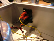
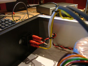
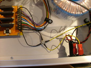
here are two pics of my build so far. Please (please!) tell me where the F*ck i'm going wrong before I electrocute myself!!!


Remember guys, i'm a complete novice, no big words!!!

I promise that once i've built this, I will think twice before taking on anything so stupid again.

Matt
 
Hi Matt,

My apologies. I actually saw your e-mail but never had the opportunity to reply. I was taking some stuff out to the civic amenity, aka "the dump".

First of all, do not be scared of the mains connections. Be careful with it but don't be scared. You are doing a great job.

What I see from the pictures is that the transformer and the mains switch is connected correctly. Let's double check.

I asked you to skip the mains selector, so it is of no concern to us at the moment.

There are two 115V primaries on the transformer with White and Yellow wires. For 230V operation you connect them in series. Yellow of one secondary connects to the White of another. These are soldered and taped up, completely insulated. I can see that you have soldered them. Apply a bit of heat shrink tubing and tape it up completely. You can fold the wire back, tape it over and tie it with a cable tie.

I can see that Yellow and White of the primaries are connected to the left/right bottom tabs of the mains switch.

Top left/right tabs of the mains switch are now Red and Black wires.

Black goes straight to the Neutral (N) tab of the IEC.

Red wire goes to the side tab of the fuse holder.

Center tab of the fuse holder connects to the Live (L) tab of the IEC.

Earth tab which is the one in the middle of the IEC connects to the chassis of the case and on the pictures you sent me you had already done that.

Unfortunately I am going to have my tea now and I'll be back to explain the LED connections.

Stay tuned.
 
sahib said:
Hi Matt,

My apologies. I actually saw your e-mail but never had the opportunity to reply. I was taking some stuff out to the civic amenity, aka "the dump".

First of all, do not be scared of the mains connections. Be careful with it but don't be scared. You are doing a great job.

What I see from the pictures is that the transformer and the mains switch is connected correctly. Let's double check.

I asked you to skip the mains selector, so it is of no concern to us at the moment.

There are two 115V primaries on the transformer with White and Yellow wires. For 230V operation you connect them in series. Yellow of one secondary connects to the White of another. These are soldered and taped up, completely insulated. I can see that you have soldered them. Apply a bit of heat shrink tubing and tape it up completely. You can fold the wire back, tape it over and tie it with a cable tie.

I can see that Yellow and White of the primaries are connected to the left/right bottom tabs of the mains switch.

Top left/right tabs of the mains switch are now Red and Black wires.

Black goes straight to the Neutral (N) tab of the IEC.

Red wire goes to the side tab of the fuse holder.

Center tab of the fuse holder connects to the Live (L) tab of the IEC.

Earth tab which is the one in the middle of the IEC connects to the chassis of the case and on the pictures you sent me you had already done that.

Unfortunately I am going to have my tea now and I'll be back to explain the LED connections.

Stay tuned.

Cemal, you once again are coming to the rescue. I am on holiday this week, and have cleared it with the missus to work solely on my rig tomorrow and Friday to get it finished (woohoo!). With your help and expert advice, my nerves are subsiding! Your instructions seem so clear. Hopefully i'm on the right track. Looking forward to checking my connections later.

By the way, this post is going to be very helpful for total newbies. I have scoured this help thread and I have been unable to find any thread that actually explains in lamens terms how to wire the PSU. Thanks as always.

Matt
 
Yeap. It is 25A big mutter fokker and it will take any sh*t thrown at it.

If you have them in stock you can certainly use the film caps but otherwise they are a luxury for that job.

I am just going back to give my son his bath and put him to bed. I'll be back.
 
sahib said:
I am just going back to give my son his bath and put him to bed. I'll be back.

i had hairwashing duties tonight. three in a row!!! all tucked up now though, and back at the workbench... cracking into the mains dude!
 
Matt,

To have continuity I copied some images from my previous post. Don't forget to do your cable management as in the below picture.

psu51x_02.jpg


2. The wiring of the secondaries does not make much of a difference as the each rail of the power supply has its own bridge rectifier. However, it is a good practice to keep everything in the same phase. The way the wires leave the transformer is actually in order. I have connected as in below image.

511colourcode.jpg


Connection of LEDS.

If you look carefully one of the terminals of the LED is longer than the other one. You may have noticed this on the electrolytic capacitors too. It is a standard to indicate its polarity. It stands for the positive (+).
The shorter one is obvioulsy the negative(-).

Now, the dual outputs of the psu contains positive (+) and negative (-). Connect these to the center tab of of their respective fuse holders.

From the edge tab of the fuse holder you take the voltage out and connect it to the 7 pin Neutrik. At the same time solder the series resistors for the LEDs to the tabs.

Then solder the resistors to their respective LEDs. Don't forget, if the output is positive then you solder the longer terminal of the LED to its respective resistor, if it is negative it is the shorter terminal.

Then take the ground from the output terminal block of the pcb using black wire to the other terminals of the LEDs to complete the circuit. Obviously if the LED is on the positive output its negative/shorter terminal will be connected to the ground. If it is on the negative output, this time its positive/longer terminal will be connected to the ground. Because the ground contains both the negative and the positive potentials.

511fuse.jpg


4. In terms of 7 pin Neutrik the pin configurations are as follows;

1 = Chassis
2 = Gnd
3 = +16V
4 = -16V
5 = +48V
6 = +24V
7 = -24V


You have some work with three kids. One is killing me already and I feel too old for fatherhood shit at almost fifty. We should have done this when we were younger. I roll with him for two minutes and I am out of breath. He is like a bloody Duracell bunny. Never stops. Here we go, he is shouting from his bedroom saying his dvd player is not working. I'll be back.
 
:D

Wow Cemal, my kind of explanations! I think I read somewhere what resistors are required for each of the LED's. I've got some kicking around. what's needed for each LED? Anything in particular?

When you say to the 7 pin neutrik... lets say i'm wiring the 16v+ and the 16v- LEDs... do I literally join the wires together (i.e. from the LED and the output terminal block) at the 7 pin?

PS: about to post some final pics of my wiring as per your instructions... be up in about 10 mins

Cheers
 
Ok, here we go.


I have left the IEC exposed so you can check my wiring. So...

the white lead from the first secondary and the yellow lead from the second secondary are now soldered and heat shrunk
The black lead from the mains switch (top right position) is now connected to Neutral on the IEC
The live from the IEC is connected to the centre on the fuse
the red lead from mains switch (top left position) is connected to the fuse outer[/list]

(to confirm (as its hidden by the fuse cover)the black lead (from IEC live) is soldered to the centre and the red lead (from mains switch top left) is soldered to the outer).

So can we confirm that this is correct?

here are some updated images:


I will put the IEC cover on and tether the wiring afterwards.

Oh,

another thing that is confusing me is that there are two chassis connections on both pcbs but only 7 pins on the neutrik. Do I connect both of them together at each end and then go point to point on point 1 of each neutrik?

 
Resistor values are on the schematic on the first page of this thread. However, calculation is not difficult. It is basically the ohms law. LED requires a certain amount of voltage to get the guys moving inside. That is called the forward voltage. It depends on the type of LED but the one you have should have around 1.5V. It also has a forward current. Again the one you have should have around 20mA. Basically take away the forward voltage from the supply voltage and divide the remainder by the forward current.
R = Vs - Vf / If

O.K. Let's connect  the 16V rail.

Take +16V from the output terminal of the pcb and connect it to the center tab of its respective fuse holder. Take the edge tab of the fuse holder and connect it to the pin 3 of the 7 pin Neutrik. Solder one side of the series resistor to the edge tab of the fuse holder, and solder the other side of the resistor to the longer terminal (+) of the LED. Shorter terminal (-) of the LED will be connected to the ground but wait.

Take -16V from the output terminal of the pcb and connect it to the center tab of its respective fuse holder. Take the edge tab of the fuse holder and connect it to the pin 4 of the 7 pin Neutrik. Solder one side of the series resistor to the edge tab of the fuse holder, and solder the other side of the resistor to the shorter terminal (-) of the LED. This time the longer terminal (+) of the LED will be connected to the ground. Still wait.

Repeat above for the other outputs.

Take the ground from the output of the pcb and connect it to the remaining terminals of the LEDs. Take another ground from the PCB and connect it to the pin 2 of the 7 pin Neutrik.

Of course I would first cut the wires to size, solder them to the 7 pin Neutrik, starting from the center pin and then connect them to their respective destination. I would apply shrink tubing to the Neutrik connections.


Good.

Only thing wrong is that you have used Black for the Live from the IEC to the center tab of the fuse. Don't do that. Always use the same colour code. Do not mix. Also I am not sure if I supplied you the wiring kit but if I did then you should have Brown for Live, Blue for Neutral and the Yellow+Green for ground wires. Thought nothing wrong with using Red for Live and Black for Neutral but generally these colours are reserved for this duty.

Same goes for the chassis ground from the PCB. I wouldn't use Black for that. Stick to the Yellow+Green
 
sahib said:
Good.

Only thing wrong is that you have used Black for the Live from the IEC to the center tab of the fuse. Don't do that. Always use the same colour code. Do not mix. Also I am not sure if I supplied you the wiring kit but if I did then you should have Brown for Live, Blue for Neutral and the Yellow+Green for ground wires. Thought nothing wrong with using Red for Live and Black for Neutral but generally these colours are reserved for this duty.

Same goes for the chassis ground from the PCB. I wouldn't use Black for that. Stick to the Yellow+Green

Noted. The right colour for the job. I'm botching that a little right now, could run into trouble there. I need to do a trip to RS in the morning actually. Will need some more wire and some resistors, but nevertheless still working my way through this wiring thing on the LEDs. Great tutorial Cemal from a great teacher. I'm loving every second of this.
 
Back
Top