official GDIY51PSU Help & Support Thread

GroupDIY Audio Forum

Help Support GroupDIY Audio Forum:

This site may earn a commission from merchant affiliate links, including eBay, Amazon, and others.
Ok, so when you guys who are much smarter then I am figure this out, I will put in either the LM317 or get 350's?  Or do we need 350's either way since that is what it was built around?  If so, I got the wrong ones in my kit.

Also, what ceramics are we suppose to have in the kits?  Mine say BC 103.  Not sure if that is the proper value either?


Thanks guys.
 
dandeurloo said:
Ok, so when you guys who are much smarter then I am figure this out, I will put in either the LM317 or get 350's?  Or do we need 350's either way since that is what it was built around?  If so, I got the wrong ones in my kit.

Also, what ceramics are we suppose to have in the kits?  Mine say BC 103.  Not sure if that is the proper value either?


Thanks guys.
Dan, Those ceramics are correct...if you choose to use them. 10 plus 3 more zeros is 10000pf = 0.01uF = 10nF. Volker calls for 10nF on his skiz. To be safe, you should use LM350T's. That is what should be in the kit.

jdbakker said:
Only if they like the smell of napalm molten silicon in the morning (but I've sung a similar tune earlier in this very thread).

I can't be bothered to do the math again, but I suspect that particularly for the 24V rail it's not possible to spec a transformer so that you can safely get 3.2A out of any regulator in a TO-220 package, even given an infinite heat sink. Keep in mind that you need to account for low line and high line conditions, not to mention component variations.

JD 'dissipation!' B.
[besides: compare the price of an extra power regulator board to that of even one typical 500-series module. The big expense is in copper and aluminium, not silicon and epoxy; you can use one (big) transformer to power two regulator boards, and two smaller heat sinks tend to be cheaper than one big one]
JDB, with mucho due respect, I hear you loud and clear! I guess it is all user and gear dependent. 51x Alliance and VPR are just guidelines. We all know that some people will not give a **** about that. Not to mention that 130mA per rail for a single 2520 style module is a lot of headroom.

My thought when typing that "2 racks from one supply" statement was this. My VP26's driving a 600ohm load draw nearly 51mA per 16 volt rail. If I add 30% to that to be safe and have some headroom, I get about 66mA per 16V rail. 66mA times say 22 preamps is just under 1.5A. Right at the limit of the LM317, well within the spec of a LM350 and right at what PSU will deliver. I'm not saying that I am gonna do this or that anyone else should do this but you can bet that someone will. Not to mention that there is no draw on the 24V rails in that example. It is highly possible that some educated user will have 11 modules in one rack running on only the 16V rails and 11 modules in another rack running on only the 24V rails. I think it is all really user and gear dependent. I suppose it is also pretty wise to do a few measurements before overloading a PSU and melting some silicon.  ;D

Best, Jeff
 
dandeurloo said:
Jeff, thanks for clearing things up! 
No problem Dan. I am far from an expert but know just enough to be dangerous. That's why we rely on the input from cats like JDB. If any of my thinking or math is flawed, please slap me around a little!  :D 8)
 
(Haven't had my morning coffee yet, so I might be making my point somewhat stronger than I normally would).

jsteiger said:
[...] Right at the limit of the LM317, well within the spec of a LM350 and right at what PSU will deliver. [...]

That's not the point (or: not my point).

At the risk of being a nag: with the transformers you're selling(/speccing) you run into thermal limits before hitting current limits, even on the LM317. National's data sheet for the parts shows that the minimum guaranteed current limit is also temperature-dependent, this factors into the equation.

(Also: the way the board is laid out, with the regs relatively close together, means that the effectiveness of any heat sink will be reduced)

jsteiger said:
I'm not saying that I am gonna do this or that anyone else should do this but you can bet that someone will. Not to mention that there is no draw on the 24V rails in that example. It is highly possible that some educated user will have 11 modules in one rack running on only the 16V rails and 11 modules in another rack running on only the 24V rails. I think it is all really user and gear dependent. I suppose it is also pretty wise to do a few measurements before overloading a PSU and melting some silicon.  ;D

From my POV it makes no sense at all. I know that I may have a rep for looking for more robustness than would fit the 'DIY spirit', but this is a no-brainer. The PSU parts and board are so cheap, cheaper even than a second power cable+connectors would be if you use the parts Sahib specified. Temperature's also a factor: two boards will run cooler than one, increasing the life of your silicon and nearby capacitors.

I'm sure there are specific situations where it would work, and if I were building a few thousand to be deployed in airport lounges (or any other temperature-controlled environment) I might consider it for cost reasons. But for DIY@qty1? If you value your time at more than McD rates, even doing "a few measurements" will very soon approach the cost of the extra board you're trying to eliminate.

Finally, it's cheap insurance. It eliminates nasty surprises. Maybe it'll work today with two racks full of VP26es. Maybe next year you'll fall in love with a batch of custom 2520 clones that just happen to draw a bit more current. You try it in one pre, works fine, sounds heavenly. You replace all of them, and you start getting intermittent faults. It works fine in winter but cuts out in summer. It works OK by itself but starts acting wonky if the adjacent PM670 is powered at the same time. Those are fun faults to chase after.

dandeurloo said:
Ok, so when you guys who are much smarter then I am figure this out, I will put in either the LM317 or get 350's?

If it were my rack I'd use the LM317s. There's little to no technical justification for using the LM350s.

JDB.
[but like I said before: I am neither selling nor offering tech support for these boards, and those who are/do should act as they see fit]
 
I must step in to express my views on this and agree with JDB. I would use one board per rack.

If the cost is of issue then reduce the reservoir cap values down to 4700uF, it is still more than ample for 1.5A current draw.  But as said this is DIY and that is why we do not care about spending few extra bucks in return for increase in reliability. Run things cool not hot.

I actually have designs of dual  PSUs that would supply 3A without a sweat. Volker and Jeff has the pictures. But they are larger in size as the components are more spread out (the reason explained by JDB).  Hence that is why I recommend using Volker's board on this project. It is beautifully laid out and much more compact, but use one board per rack.
 
only one PSU PCB for one Rack is recommended.
all other scenarios are on your own risk!

grantlack said:
sure, safety's nice and all... but yellow and red is so much more 51x!

green and red would make me think 51x-mas  ;)

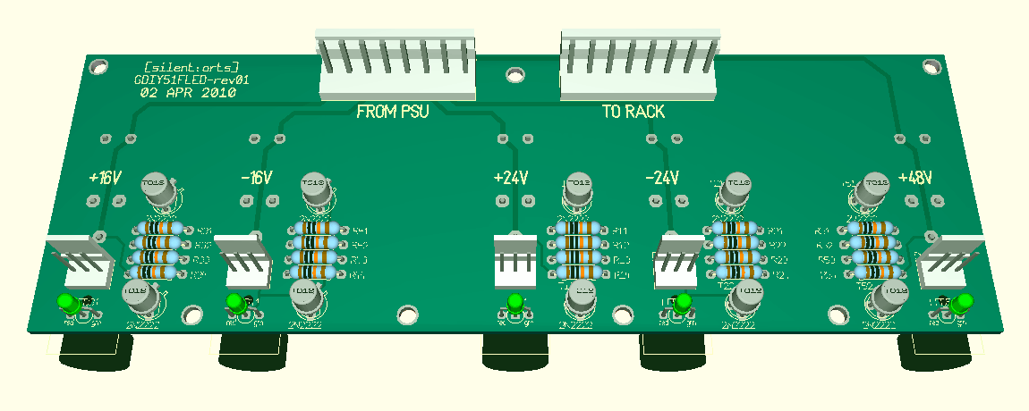
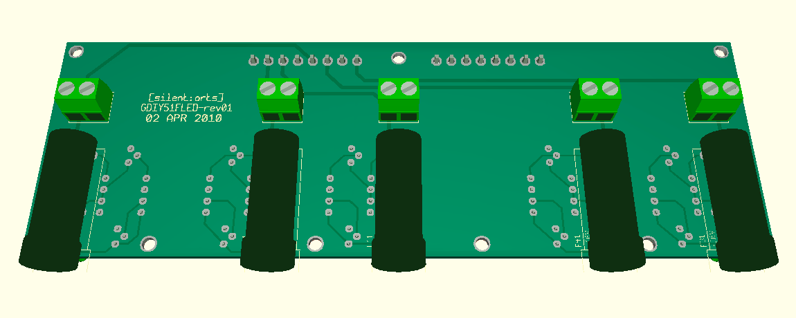
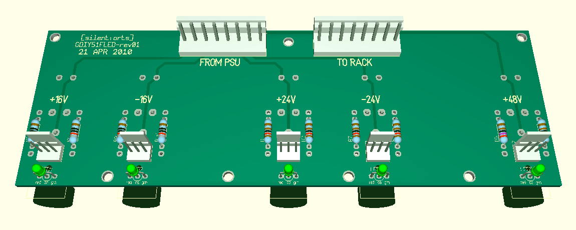
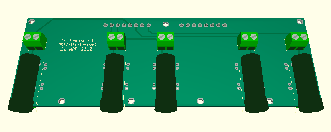
to show you the difference:
green / red / black:
top
GDIY51FLED-GR-Top.gif

bottom
GDIY51FLED-GR-Bot.gif


yellow / red / black:
top
GDIY51FLED-YR-Top.gif

bottom
GDIY51FLED-YR-Bot.gif


note, there are screw block terminals for off board fuse holders, and molex connectors for off board LEDs.
PCB size is the same, thus the same price for both versions.

to simplify and to be not affected with christmas I will prefer yellow / red / black ;)
needs two different styles of be-colored LEDs. but we can supply them with the PCBs.
(while I'm everything but not a german patriot, black / red / yellow is ... )
 
Ptownkid said:
So the second one takes less parts...?
sure.

yellow (all fine) / red (PSU fine but fuse broken) / off (PSU rail is dead) can be done "passive".
red from the PSU rail before the fuse, green after the fuse. that is it.
you need common cathode and common anode be-colored LEDs since we have positive and negative rails.

green (all fine) / red (PSU fine but fuse broken) / off (PSU rail is dead) needs some "active" switching logic.
Cemal did a nice job on this, and all 5 rails can use the same type of be-colored LED.

this PCB will be an option and is not needed. due to the size and needed copper weight (same as the PSU PCB) it won't be cheap.
you don't need it for the PSU, it is just an unnecessary add on!
but a nice and professional one  ;D
 
A regulator question for guys in the know...if the supply is pumping out a full 1.5A, will the 3A LM350 run any cooler than the 1.5A LM317? I am just curious as the LM317's heat up rather quickly with a 1.5A load on my supply. The do get pretty toasty too.  :eek: Pardon me if it has already been mentioned somewhere.

Cemal, we need those cool heat sink extrusions like you have!  8)
 
No, as previously stated both have the same TO220 package and a thermal limit of 125 deg C, so there's no advantage to the LM350. They will both hit the 125 deg C wall at the same time. The real task here is to try to keep the temp below that thermal shutdown limit while delivering the required amount of current. That can be difficult to do (even with forced-air cooling). Designer's will instead factor in all of the enviromental variables, and derate the regulator to a real world value.

My two cents:
I think that you should maybe consider a different style of heatsink. For example: http://search.digikey.com/scripts/DkSearch/dksus.dll?Detail&name=HS380-ND

Although it doesn't look as massive as the "L" bar of aluminum, it has better dissipation qualities. Look at all the surface area it has compared to the "L" bracket, and it is all relatively close to the transistor's junction. And it's thermally (and electrically) isolated from the other regs and not trying to dump heat into the same chunk of aluminum.


Nice project by the way!
 
L bracket is there to facilitate a convenient mounting. For better efficiency we can modify it to allow the large finned heatsink on below page to have a direct contact with the regulators.

http://www.groupdiy.com/index.php?topic=36874.40

 
Well I missed that!  :-[ If you can go right onto that sink with the regs, that would be pretty sweet. Has anyone really tested/tortured/documented this psu yet? High line voltage, plugged vents, etc...?

For me personally, if I weren't worried about absolutely having 130mA available for every slot of every rack (and I'm not, as an end-user), I wouldn't hesitate on daisychaining up a couple racks and just keeping an eye on the draw whenever I'm changing out or adding modules. I'd just add some amp meters to the front panel...

And maybe some over-voltage protection...
 
Won't be be a problem.

However, I think the way things are going I am going to end up designing an add-on supervisory circuit with overload/temperature protection, metering etc. I'll check what sort of low cost metering available and try to design the schematic before I leave to return to UK.
 
jsteiger said:
Crusty2 said:
...I'd just add some amp meters to the front panel...
I thought about this last night too. That would be super sweet Cemal!  8)

i was looking into doing this digitally a couple weeks ago, but school is taking precedence over brushing up on my (very basic) hex reading/writing.  there are some pretty cheap 2x16 red on black LCD boards to be had out there.  a temp readout would be handy too, great thought Cemal!
 
hello,
this is possibly a bit of a newb question, but i was 'gifted' a number of 18v, 1A center tap transformers from the lovely Bob Moses, and i was thinking of using these(in lieu of not having a current N. American toroid) to gather the 16 and -16 rails, and get my power supply up and running for the time being. what would be the best way to ultilize these? I know the power supply is designed with no center-tap on the windings. should i use 2 sep. transformers and hook the centertaps to ground, using the 2 secondary windings of each? I have a 48v transformer as well, and figure i could just cobble them all for the time being. (i don't currently need the 24v rails)
Thanks
Ian
 
imo said:
... I know the power supply is designed with no center-tap on the windings ...
you understood the most important thing :)

don't know why, but here in europe center-tap transformers are not very common.
we normally have dual secondaries. very handy for this type of PSU ...

imo said:
... should i use 2 sep. transformers and hook the centertaps to ground, using the 2 secondary windings of each? ...
yes, you will need 2 sep. transformers. don't hook any wire from the transformer to ground.

if someone could enlighten me:
is 18V center tap one 18V secondary with a center tap (=2x9V),
or one 36V secondary taped to 2 x 18V?
I'm always stuck there ...
 

Latest posts

Back
Top