[pix] [finished] Germanium Preamp

GroupDIY Audio Forum

Help Support GroupDIY Audio Forum:

This site may earn a commission from merchant affiliate links, including eBay, Amazon, and others.
WHAT???

when did I miss what was going on in this thread??

I remember looking at the original pics but now there are preamps coming with haufe trannies in the future??

Did Silent Arts say that there will be a 500 series from this too?

You guys are going to make me starve to death cause I'm going to have to buy this if/when it comes out regardless of how my bank account feels about it.  I was seriously going to start trying to source parts for a germanium preamp and that is why I came back to this thread...

:D

 
Svart said:
... Did Silent Arts say that there will be a 500 series from this too? ...
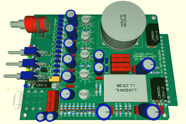
yes. but due to the 24V it will be an 18pin card, not compatible with any lunchbox or original API rack.
I already bought 50 pieces of NOS ASY26 and will offer them too.

for the timing I'm feeling guilty - Kubi already send me one of his home made PCBs for doing a test build, but I didn't have had the time to start it yet ...

but this project will definitely come, in four versions:
- complete documents for home-etching Kubis standalone version
- complete documents for home-etching my 51x version (if somebody wants to do this, it is double sided)
- factory made PCBs of the stand alone version
- factory made PCBs of the 51x version, may be some kits with the metal work & transformers

Jensamp51X_rev03-Haufe3D.png


be patient :( :eek: ;) ;D
 
I think this might have problems with DIY builders that don't know things like ohms law.

 The 4 output transistors look like they will need to be matched NPN to NPN and PNP to PNP.

EDIT NPN to NPN and NPN to NPN

On the proto builds what is the voltage difference between Q4 and Q6 collectors and emitters and bases or Q3 and  Q5 collectors bases and emitters?
 It also looks like you will need to match all the resistors side to side in the output section.  Also being a output stage the cheap DMM hfe will most likely not work well enough.  Should be curve traced or Hfe matched at three Ic points in the operation range in the circuit.

Maybe the proto build is fine because the parts were from the same batches.

I would look for higher power devices that have high enough hfe for a 2 device output section.
 
I did mean it in a good way.  If I was to sell something on a large scale I would try to make it as reproducible as possible.

transistors like TIP29 and TIP30 might work if the dual output works.  The TIPs have less hfe however you will only be driving one base and not two so you will have more current drive to one device

EDIT two TIP29s the TIP30 is PNP
 
Gus said:
I did mean it in a good way...
Gus, me too. I just like it - and it is just true. for many projects around here.

Gus said:
If I was to sell something on a large scale I would try to make it as reproducible as possible.
this is a good idea. I doubt a large scale, but this is a matter of definition.
for me it is only doing (and selling) the PCBs. the design of the circuit,  the decision which parts to use, is the part for the designer of the circuit (in this case Kubi)(mainly - sometimes I substitute due space limitations).

but thanks for the suggestions, if Kubi finds the time (he is very busy at the moment) he might comment the suggestions you did.
 
Heya Gus, maybe a project that needs this kind of work is good for the noob DIYer?  Maybe it would force a person otherwise content with just stuffing boards into actually troubleshooting the unit and learning something? 

If my CD player(first generation!) hadn't broken and I hadn't been so poor that my only choice was to fix it, then I wouldn't have gotten into electronics in the first place.  Maybe necessity is the mother of invention but being broke is the father of troubleshooting?  ;)
 
Volker I forgot to add build in my first post

I think this build might have problems with DIY builders that don't know things like ohms law.

is what I meant to post

I don't have an issue when people build from a kit or PCB and parts you need to learn some way.

Use it if you want.
 The only issue is it might sound harsh to some people but it was not meant that way.  In this case matching would be the harder part of the build and matching would require using ohms law to pick resistors for different Ic(collector current) when making a test jig for the transistors to measure them at operating currents.
This is if matching is necessary I don't know because I have not built this but it looks like it is to me for min distortion.  Yes it will work because of the cap coupling from each output pair :however the outputs might be at different places and sum up different.  

 
Gus said:
I think this might have problems with DIY builders that don't know things like ohms law.

  The 4 output transistors look like they will need to be matched NPN to NPN and PNP to PNP.

On the proto builds what is the voltage difference between Q4 and Q6 collectors and emitters and bases or Q3 and  Q5 collectors bases and emitters?
  It also looks like you will need to match all the resistors side to side in the output section.  Also being a output stage the cheap DMM hfe will most likely not work well enough.  Should be curve traced or Hfe matched at three Ic points in the operation range in the circuit.

Maybe the proto build is fine because the parts were from the same batches.

I would look for higher power devices that have high enough hfe for a 2 device output section.
Forgive my newbiness, but if I refer to the schematic:
http://audio.kubarth.com/jensamp/jensamp_schaltplan.gif
The 4 output transistors are NPN, no ? Looks like 2 emitter followers in parallel
Does the transistors current flow really need adjusting in a precise way ? again sorry for my question,
I am actually learning about transistors :)
 
Back
Top