


> My first discrete project is going to be a moving-coil phono cartridge - to - line - level preamp
Sorry I missed this remark.
Phono preamps are tough; IMHO even tougher than good mike amps. MC phono has extra challenge. I don't think it is a good starter design.
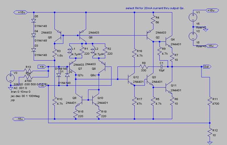
The schematic you posted will work. It seems over-complicated for the job.
Your Stage_1 has the doubled-outputs, but the real load is R13 1K which can't possibly need over 10mA-13mA peak (and much less over most of the audio power-band).
OK, you also have to drive your 150+1Ω feedback network. Why 1Ω? Because your MC needle output is low and you want a low noise voltage, of course. But then you have R27 R28 220Ω each. Your input noise voltage is like a 440Ω resistor, plus the few-Ω needle coil, plus the 1Ω NFB resistor, plus the emitter dynamic resistances of about 300Ω each. Around 1,000Ω total noise resistance. Only a few ohms of that is source (good) resistance, the rest is just thermal noise.
So there is no reason for the NFB net to be 1Ω. 100Ω would be fine, much lower than the total 1K noise resistance, making R7 say 15K, so Stage_1 output only needs 15mA peaks, 8mA idle current, one output pair should be plenty.
OTOH, your source resistance (MC phono) is few-Ω, so can generate an electrical signal with thermal noise voltage like a few Ω, much lower noise voltage than your 1KΩ amplifier input noise. Transformerless MC phono inputs usually use HIGH bias currents to get low transistor dynamic resistance. The transistor parasitic resistance limits how low it can get, but several mA of bias current in a big-junction transistor is about as good as it gets without exotic parts. So for lowest noise with MC phono input, you should consider 1mA-2mA in each input device, with preferably zero emitter resistance, or at least less than few-Ω. However the output stage does not need much more than that to drive the RIAA EQ network. You don't need a many-stage amplifier.
When working at these noise resistance levels, diff-pair inputs double your noise resistance. They are a necessary evil in balanced-mike work, but not in home phono work.
And also: you do not need a "zero ohm" output, you need 1,000Ω into your RIAA network. For general mix-n-match hook-up, zero-Ω outputs are nice. But when the job calls for a specific load or output impedance, building that into the design tends to be simpler than aiming for some "ideal" and then padding-out to the specified impedance.
Also, you don't need a zero-volt DC output. You need C2 to set your 20Hz RIAA pole, and RIAA is actually zero response at zero Hz. As long as you need a cap, there is no point in great DC accuracy.
Look at another fact. Up through 2KHz, your EQ network has a loss of no more than 8:1. Your output stage has gain of 150. So the level out of Stage_1 can not be more than 1/20th of the level out of Stage_2. Stage_1 can be a MUCH lower-level design. I'm forgetting the fact that the RIAA loss will be 80:1 at 20KHz, 800:1 at 200KHz, etc. Music power declines above 500Hz, but some material has ample 6KHz power. Still Stage_1 runs at no more than 1/6th the output of Stage_2. It could run on +/-3 rails! Or it could be designed very inefficiently and simply.
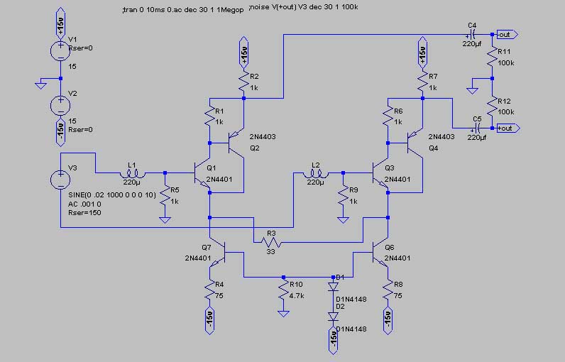
This should work for Stage_1 and be lower noise:

I've loosely based this on National.com's AN222 fig 4, which is a low-noise MC preamp.
The output impedance IS 1K, so the RIAA network series resistance is already there.
The gain is almost 1,000/6 or 150, close-enuff.
The noise resistance is about 15Ω on paper, about 50Ω with available devices (parallel LM394; selected 4401 may be similar), much lower than your 1K noise-resistance design. Over 10dB lower noise floor for few-Ω sources. I've omitted an input cap, a nasty source of subsonic noise. The 4,700uFd cap is in the same place as far as noise, but has to be so big that its noise is a non-issue. (It also has some DC bias to keep an electrolytic formed.)
You may need an extra ripple filter on the + rail, since the output is really referenced to the rail not to ground. 100Ω and 4,700uFd ought to clean it good. You can do the same on the - rail but it has over 40dB of rejection already.
Output swing is over 3V peak. Around 6KHz the RIAA is 1/24, the output 150/1, so the output will be (trying to) swing 18V peaks before this stage clips. At typical MC cartridge sensitivity and recorded levels, this stage's output will be 1V or less.
And you might use this scheme for Stage_2 too. In the top of the audio band, the source impedance into Stage_2 is falling from 120Ω. Noise is mostly determined by Stage_1 noise, but in the top octave a 1K noise resistance amp as Stage_2 may not be masked by Stage_1 noise. If you do that, raise the 270Ω resistor to maybe 1K. The peak swing of 3V is more than enough to toot a line-level input. CD player ab-max output is 2.8V peak. Depending on your cartridge sensitivity, it might try to make more than that. Make R9+R11 a 5K pot (with 50K in parallel to preserve the computed EQ), play your hottest LP, and set level similar to a hot CD or a bit less.
Sorry I missed this remark.
Phono preamps are tough; IMHO even tougher than good mike amps. MC phono has extra challenge. I don't think it is a good starter design.
The schematic you posted will work. It seems over-complicated for the job.
Your Stage_1 has the doubled-outputs, but the real load is R13 1K which can't possibly need over 10mA-13mA peak (and much less over most of the audio power-band).
OK, you also have to drive your 150+1Ω feedback network. Why 1Ω? Because your MC needle output is low and you want a low noise voltage, of course. But then you have R27 R28 220Ω each. Your input noise voltage is like a 440Ω resistor, plus the few-Ω needle coil, plus the 1Ω NFB resistor, plus the emitter dynamic resistances of about 300Ω each. Around 1,000Ω total noise resistance. Only a few ohms of that is source (good) resistance, the rest is just thermal noise.
So there is no reason for the NFB net to be 1Ω. 100Ω would be fine, much lower than the total 1K noise resistance, making R7 say 15K, so Stage_1 output only needs 15mA peaks, 8mA idle current, one output pair should be plenty.
OTOH, your source resistance (MC phono) is few-Ω, so can generate an electrical signal with thermal noise voltage like a few Ω, much lower noise voltage than your 1KΩ amplifier input noise. Transformerless MC phono inputs usually use HIGH bias currents to get low transistor dynamic resistance. The transistor parasitic resistance limits how low it can get, but several mA of bias current in a big-junction transistor is about as good as it gets without exotic parts. So for lowest noise with MC phono input, you should consider 1mA-2mA in each input device, with preferably zero emitter resistance, or at least less than few-Ω. However the output stage does not need much more than that to drive the RIAA EQ network. You don't need a many-stage amplifier.
When working at these noise resistance levels, diff-pair inputs double your noise resistance. They are a necessary evil in balanced-mike work, but not in home phono work.
And also: you do not need a "zero ohm" output, you need 1,000Ω into your RIAA network. For general mix-n-match hook-up, zero-Ω outputs are nice. But when the job calls for a specific load or output impedance, building that into the design tends to be simpler than aiming for some "ideal" and then padding-out to the specified impedance.
Also, you don't need a zero-volt DC output. You need C2 to set your 20Hz RIAA pole, and RIAA is actually zero response at zero Hz. As long as you need a cap, there is no point in great DC accuracy.
Look at another fact. Up through 2KHz, your EQ network has a loss of no more than 8:1. Your output stage has gain of 150. So the level out of Stage_1 can not be more than 1/20th of the level out of Stage_2. Stage_1 can be a MUCH lower-level design. I'm forgetting the fact that the RIAA loss will be 80:1 at 20KHz, 800:1 at 200KHz, etc. Music power declines above 500Hz, but some material has ample 6KHz power. Still Stage_1 runs at no more than 1/6th the output of Stage_2. It could run on +/-3 rails! Or it could be designed very inefficiently and simply.
This should work for Stage_1 and be lower noise:
I've loosely based this on National.com's AN222 fig 4, which is a low-noise MC preamp.
The output impedance IS 1K, so the RIAA network series resistance is already there.
The gain is almost 1,000/6 or 150, close-enuff.
The noise resistance is about 15Ω on paper, about 50Ω with available devices (parallel LM394; selected 4401 may be similar), much lower than your 1K noise-resistance design. Over 10dB lower noise floor for few-Ω sources. I've omitted an input cap, a nasty source of subsonic noise. The 4,700uFd cap is in the same place as far as noise, but has to be so big that its noise is a non-issue. (It also has some DC bias to keep an electrolytic formed.)
You may need an extra ripple filter on the + rail, since the output is really referenced to the rail not to ground. 100Ω and 4,700uFd ought to clean it good. You can do the same on the - rail but it has over 40dB of rejection already.
Output swing is over 3V peak. Around 6KHz the RIAA is 1/24, the output 150/1, so the output will be (trying to) swing 18V peaks before this stage clips. At typical MC cartridge sensitivity and recorded levels, this stage's output will be 1V or less.
And you might use this scheme for Stage_2 too. In the top of the audio band, the source impedance into Stage_2 is falling from 120Ω. Noise is mostly determined by Stage_1 noise, but in the top octave a 1K noise resistance amp as Stage_2 may not be masked by Stage_1 noise. If you do that, raise the 270Ω resistor to maybe 1K. The peak swing of 3V is more than enough to toot a line-level input. CD player ab-max output is 2.8V peak. Depending on your cartridge sensitivity, it might try to make more than that. Make R9+R11 a 5K pot (with 50K in parallel to preserve the computed EQ), play your hottest LP, and set level similar to a hot CD or a bit less.


")