PRR VariMu "Bluebird" mod help!!

GroupDIY Audio Forum

Help Support GroupDIY Audio Forum:

This site may earn a commission from merchant affiliate links, including eBay, Amazon, and others.

illacov

Well-known member
Joined
Nov 13, 2008
Messages
79
Does anyone have the bluebird schemo's of his modded PRR VariMu?

I have a couple of guys looking at this schematic and we needed some help with the usages of the interstage/bridging transformer.

Without seeing the schematic, I'm only guessing about it. I can't really tell if guys are using the interstage transformer instead of an output tranny? Or if they are using it in conjunction with an output transformer as well??
I ordered a set of PCBs and they should be arriving in the near future.

The schematics were posted before but now they are gone. I would greatly appreciate any help with this. There is another help thread but one not focused on bluebird's (and others) usage of bridging transformers etc...

Any help on this??

Peace
Illumination
 
I sent bluebird an email about a week ago trying to get the schematics, but I've had no reply yet. I hope someone else has it too.

Matt
 
why do you want to mod it even before you buillt it?.
..it's great the way PRR designed it and I doubt it would be better with the mods Bluebird suggested in his thread( no disrespect to Bluebird thou...)...different yes, but probably not "better". ( if it is the mods I remember...it's been a while since I saw the thread..)
build it as designed first and mod it after you got it working. that way it will be much easier for people to help if you get stuck and you'll be working from a verified schematic, and later, a working build...
j
 
Hi

I don't think you actually need a schematic to apply the bluebird mods to the prr comp. In a fast varimu you really want an interstage transformer (try to read the posts from prr about this topic),  and what bluebird did, was to simply use a hi-z (10.000 to 600 Ohm I think) interstage instead of the lo-z one prr suggested. And he changed the tubes to some real variable mu tubes (6bc8, could be ecc189 also) instead of the 12au7s, adjusted the plate resistors to 4.7k and that was it for compressor part.
After the interstage transformer he split the audio in front of the 5532 opamp and used a discreet opamp for the make up gain, with a transformer afterwards, as I recall. Read all the posts about varimus that you can find, and you will be a lot wiser afterwards. This forum is an incredible source of information.
Or just build the prr comp as on the pcb. I am shure it will work just fine.
What I found interesting about prr's compressor cicuit is, that it is a great starting point for your own experimentations. You can wire the tube part point to point easily and use the circuit board for the sidechain, which is a great sidechain, as long as you do not need more than 8 or 9 volts of control voltage. Which is fine as long as you use the tubes with lowish plate voltage (like prr) and don't need more gain reduction than max. 20 dB, which is plenty enough for me.
 
Sorry for my ignorance but since you've chimed in with some intriguing information and have gotten my attention, I would love to know where the interstage transformer would be installed? Am I mistaken or wouldn't this result in 3 transformers per channel? (Input, interstage and output?)

If so thats great, I love the idea of adding more iron. The question is where does this interstage tx go? Sounds like its replacing the output transformer since PRR didn't have an interstage transformer in his original design, interesting  :eek:

The part where he splits the audio to the 5532 is a little confusing. I thought he replaced the 5532 with the John Hardy 990?

Hmm..

A few things to sort out here.

Peace
Illumination
 
Well, there is an interstage in the original design. It is right after the 12au7tubes, with the 1k resistor across the primaries. The secondary goes into the 5532, which drives the output and the sidechain at the same time. Remember, prrs goal was to present the cheapest/easiest way to build a working varimu compressor. So the output is unbalanced -10dBV, the same with the input.
Bluebird split the audio right after the transformer, so the 5532 is there for the sidechain only.
 

Attachments

  • Comp5update.jpg
    Comp5update.jpg
    121.6 KB
See that's what I thought.

So the output transformer that Bluebird used was in conjunction with that John Hardy 990 then...

The confusion came from people referencing an output transformer, I only saw transformer out on the schematic, not interstage hence my confusion.

So when Bluebird used that 990 opamp, the 5532 is working only on the sidechain? He just bypassed the audio output from the 5532 then? And we only would hear the made up gain (post compression) from the 990 feeding an output transformer?? :eek:

I appreciate your help with this, the schematics would really help to shed some light on things, if they are available plus many other members want to see the Bluebird schemo.

Peace
Illumination


So when Bluebird used that 990 opamp, the 5532 is working only on the sidechain? He just bypassed the audio output from the 5532 then? And we only would hear the made up gain (post compression) from the 990 feeding an output transformer??
Yes.
I appreciate your help with this, the schematics would really help to shed some light on things, if they are available plus many other members want to see the Bluebird schemo.
Well think about it, in this link: http://www.groupdiy.com/index.php?topic=28183.20 everything is laid out pretty clearly.
Put a 100k pot in front of the 990 for volume control, give the opamp some reasonable gain, put a transformer of your liking after it and you are done.
And isn't experimenting the great thing about diy. Especially a varimu is something where you can try a lot. Not so many parts in the audio chain, but nearly everything you change makes an audible difference. Loading of the interstage, matching of the tubes, the operation point of the tubes, plate voltage ... and so on.
It is is time consuming, but it is fun.
I went through all that, when I find the time, I will present the result here in the lab.
 
I'll be a little more specific and tell you what I did, but I don't have a drawing to send  so read carefully cause I'm going to be referencing 2 schematics.

Get/google the universal audio 176 schematic  ( I think waltzing bear has it)
the PRR schematic I'm referencing is the one posted above.

BTW I was able to do all of this by just drilling a few extra holes on Kent's existing dual PRR layout .

HERE GOES!

I used the exact same values for the 6bc8 section as are shown on the 176.
The schematic drawings are quite a bit different, but the circuits are nearly identical.  

you'll be changing R1, R2  and the R32 pot on the PRR to the values shown on the 176.  

I added the plate balance pot from the 176 at the point marked 100v on the PRR

I added R5,R6,R7, andR8 from the 176 in place of R32 (prr) in the cathode balance section.

the 176 has a pad in front of the tubes. I skipped that so the connection from transformer to grid and R4 and R33 (prr) dont change.

The B+ on the 176 is exactly the same as the PRR so you don't have to change the powersupply at all.

I used a jensen 4-1 transformer (which is something like 30k to 2k) but an edcor 10k to 600 interstage sounded almost as good...

but this also meant that I needed a bit more gain out of the sidechain so I changed R17 (PRR) for a 10k trimpot.
this also helps me balance out my left and right channels to make up for differences in tube compression/gain.

Send signal offboard to your output amp at the point in between the interstage trafo (marked TXout on the PRR schemo) and the +input of the 5532

I used a neve ba238 with a 100k trimpot at the input of the Neve (once again, this allowed me to eliminate/calibrate  any small differences between my Left and Right channels.

The meter gave me the most troubles.
A 1milliamp meter (as listed on the original PRR schematics)didn't work for me
If you look at R10 and R11 on the 176 you'll see that the meter is fed with the same circuit but different values than the PRR.  With a 500milliamp meter R3 (PRR) was a little too low, my meter wasn't zeroing correctly and it was swinging too wildly, but if I used the 176 values (330r with a 1k pot)value I was losing compression.  I don't remember exactly what I ended up with for those two but it was in the middle somewhere maybe try a 500r pot and 47r.  I think this has to do with the way the sidechains are summed together

I used stepped switches for the attack and release settings, so I can switch my sidechain summing off If I want to do some tracking through this bad boy.
Due to panel space I only have one switch for attack and one for release and  I don't get to choose individual settings in that situation  but I can live with that.

Mostly it's on my 2 bus and I f**n dig it and it blows peoples minds...

Hope that works for you.
Kelly
 
Now thats definitely eye opening.

What I didn't catch is where the audio from the output amp comes back into the circuit??

Call me crazy but you only mentioned summing, but not where it occurs. I don't think it was mentioned or was it?

It seems like if you have a mult/split before the 5532, you'd result with two independent signals which need to be summed together.

What or how are they being summed together? With resistors?
I'm not the greatest with schematics but I see that in the normal schematic, it appears the 5532 feeds the output directly. Others mentioned that its used just for the sidechain if you use something else like a 990 etc to make up that gain.

I think you mentioned something along the lines of sending the audio offboard??

What's your take on my idea to shoot that audio out to a preamp and then back in? If we can do something like a mult off the run to the interstage tx and hit it with possibly an Rshunt, we could try to get that signal at 150 ohms run it into a preamp and then shoot the 600 ohm load back into the vari mu.

Is this similar to what you're doing with that neve stage but you did it internally??

Like a baby bird, MORE MORE!! ;D

Thanks a bunch 8)

Peace
Illumination
 
this might help, but i think you need to try to look at the original schematic some more, so that you understand what is being changed and why...

ed
 

Attachments

  • prrmod.jpg
    prrmod.jpg
    68.8 KB
Regarding the 990 in the schematic above, I realize it is probably drawn for experimentation purposes and the circuit details and component values are not etched in stone. But a couple of suggestions, just in case:

1. The 10k pot from the inverting input to the 470uF capacitor (with the other end of the capacitor going to ground) needs a fixed resistor in series with it to limit the maximum gain adjustment. As it stands, the gain of the 990 is adjustable from roughly 12dB to INFINITY. I realize that this may just be a quick and dirty way to find the proper final gain, then replace it with a fixed resistor. But even for experimenting, I suggest adding a fixed resistor.

2. There should be a small-value capacitor in the feedback loop, in parallel with the 20k resistor, to limit the bandwidth well above the audio bandwidth and to keep things stable. It could be 47pF or so, but it is not a critical value. Its absence is the critical issue.

3. You could use the Jensen JT-OLI-3 "output isolator" in place of the 47 ohm resistor at the output of the 990 going to the output transformer. This would provide essentially zero-ohms impedance in the audio bandwidth due to the inductor, but 39.2 ohms above about 220kHz as the impedance of the inductor rises above that of the 39.2 ohm resistor. Results will vary depending on which output transformer is used, but Jensen generally recommends the lowest possible output impedance from the op-amp that is driving the output transformer. The 47 ohm resistor provides an output impedance of (uhhh.......) 47 ohms in the audio bandwidth (and everywhere else). The JT-OLI-3 provides zero-ohms in the audio bandwidth, but 39.2 ohms well above the audio bandwidth to provide isolation of cable capacitance from the output terminal of the 990 at frequencies where the capacitance could suck the feedback signal to ground instead of letting it go around the feedback loop as it should.

John Hardy
 
illacov said:
Now thats definitely eye opening.

What I didn't catch is where the audio from the output amp comes back into the circuit??

the output amp doesn't come back into the circuit, it's there to makeup gain lost by compressing the signal and for umm output.

Call me crazy but you only mentioned summing, but not where it occurs. I don't think it was mentioned or was it?
Crazy. 
I'm talking about sidechain summing. you would only do this on a stereo version, and it takes place at the spots marked R on the schematic. 
I had to read Kent's instructions a few times to really get a handle on what was going on there.  It also helps to read about or better yet build Keith's Ultimate SSL , there's serious knowledge happening in that thread.
It seems like if you have a mult/split before the 5532, you'd result with two independent signals which need to be summed together.

I'm not the greatest with schematics but I see that in the normal schematic, it appears the 5532 feeds the output directly. Others mentioned that its used just for the sidechain if you use something else like a 990 etc to make up that gain.
in the original the 5532 IS the output AND it's the first stage of the sidechain- in this case it's functioning as a buffer amp and can be used to give the overall sidechain a little more oomph and thus more gain reduction.
I think you mentioned something along the lines of sending the audio offboard??
this is what you call the mult.
What's your take on my idea to shoot that audio out to a preamp and then back in? If we can do something like a mult off the run to the interstage tx and hit it with possibly an Rshunt, we could try to get that signal at 150 ohms run it into a preamp and then shoot the 600 ohm load back into the vari mu.

Is this similar to what you're doing with that neve stage but you did it internally??
Nope
none of this is necessary because you're  confusing the output amp and the sidechain amp.

Try and  block out the stages of the compressor ( I like to mark up the schemos with highlighter pens) and read up a bit more on how the varimu works. I'm sure you'll be flying in no time.
Kelly
 
Hi everyone...

This is excellent material... Just what I was looking for. I am also building a Drip 175b and am adapting some of those features to the PRR.

I have almost completed a schematic with the mods discussed in this thread plus the sidechain filter me and Illumination talked about in another thread.

As soon as they are done I will post them.

I was thinking of an output stage and now we got the 990, thanks....
I would now like an input line booster to control the compression. Do you guys think the 990 on the input will work as well?

J

 
Thanks a bunch guys!

Any takers besides Matthew on if its possible to add a sidechain filter to this schemo, like the SSL side chain or a hardwired 180hz sidechain hpf??

Peace
Illumination
 
Any takers besides Matthew on if its possible to add a sidechain filter to this schemo, like the SSL side chain or a hardwired 180hz sidechain hpf??
That is easy. Just put a capacitor (something like 0.5 mF) in series with c8 and the threshold pot, make it switchable and voilà, there you go.
Do you guys think the 990 on the input will work as well?
  You won't need that, just put an attenuator in front of the input tranny and you will be fine. The comp swallows -10dbV Signals fine, but you will hit it probably harder (Well, I do) and then you have to attenuate your signal anyway.
 
Hello,

Very sorry I don't check my pm's that often...

hop.sing summed it up perfectly. and Kelly is a buddy and has a lot of experience with this thing.

I'm not sure where the schematic is that I posted but what edanderson posted is basically it. I did use 4.7K plate resistors.

OK heres the thing...I tried edcor PCB mount transformers (the larger size) and they don't work well at all with this. There must not be to much inductance in the windings of the edcors because the input attenuator severely messed with the freq. resp. The original input transformer was a cinemag and the interstage I used was a vintage triad that could handle a bit of DC. this seemed to be the best combination.

Build it try it.
 
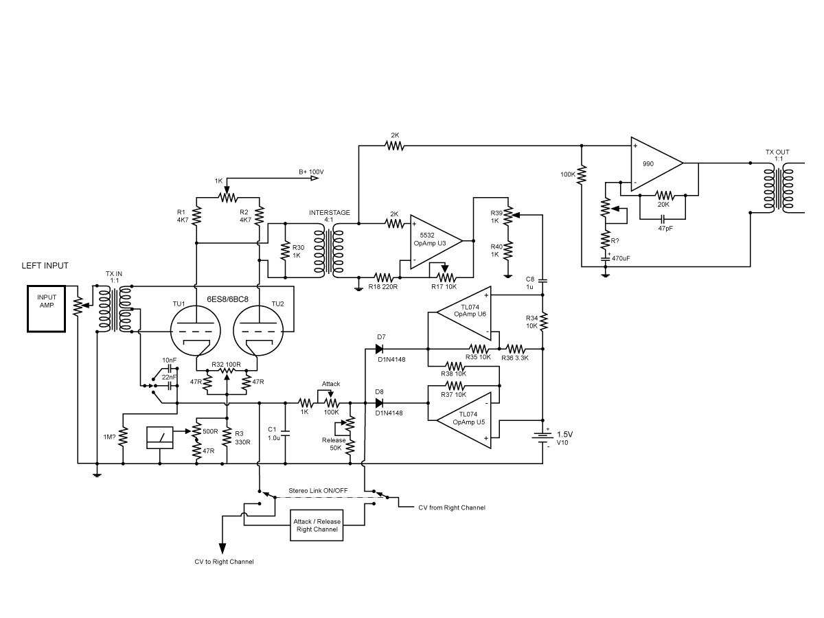
Here is the schematic.

I took all the suggestions from all the threads I've been reading about the PRR but mostly from this thread.

Like "Sleeper" suggested I used info from the UA 175b schematic to mod the cathode and plate balance trim pots and change the plate resistors. Could someone please check if I did it right? Sleeper I also used your values for the meter even thou they are vague, I thought it would be a good starting point.

I put a filter on the CV based on the filter in the G9. Is the 1M resistor necessary? From my understanding of filters, the bass frequencies need a route to earth right? So a resistor is needed or can I just leave this component out.

I tried to think of a way of linking the sidechains of a dual unit on and off. I plan to build 1 stereo unit and one dual mono with stereo link. I think this DPDT switch will do the trick.

John Hardy, I've made the alterations you suggested apart from the "output isolator". I'll do this at the next stage, once people help me identify any errors / improvements I'll complete this schemo.

I'd appreciate if anybody could double check this schemo. It would be great if we can all agree on what are good mods and collectively produce some nice documentation, schematics and BOM for a scooped up PRR Vari-Mu.

What do ya think?

PRR-Mods.gif

 
Hello Matthew,

The 1M resistor is not necessary. Don't put the caps there either. they will block the DC going to the tube grids. the High Pass filter caps should go where C8 is. Start with a .0047uf as a second choice to the 1uf. this will stop the low end from being compressed.

As far as the side chain is concerned stick to the original PRR design. It is the whole reason this sounds as cool as it does. I messed with the the attack and release resistor values a bit but that was it.

I wouldn't make R17 variable, keep it 2.2K. r39 is enough variation.
 
Hi Ian, good to see you today!
Matthew here's a few corrections for you.
First, I'd do what the Bird says. especially with regards to the sidechain and that part where it feeds back into the grids.  I had thought about copying the center tap feed back as on the 175 but I didn't have a center tapped transformer AND I never got around to it AND I was happy with the 3.3ks as in the original PRR circuit. 

the attack release switching isn't right and neither was my explanation. 
the way I did it you do join the L and R sidechain where you have shown (just after the diodes)  this way the sidechains sum together so whichever side is loudest compresses both sides of the mix equally. 

you could go as far as having two sets of attack/release controls on the front panel, because this is what you are working with.  but to conserve panel space and setting headaches you use 2 pole switches with the stepped values as shown in the chart on Kents varimu PDF (or you can use any stepped attenuator calculator)
If you plan on using the unit for a lot of dual mono tracking it might not be such a bad idea to have two sets of controls, but you don't want these to be pots because you wont get good matching in stereo mode.
Kent has some other way of summing the sidechain but I didn't like it much.

Ian and I discussed it today and he used PRRs the meter section exactly as drawn with a 1ma meter and it worked. 
I used r3 at about 47ohms (not 330) and the 500ohm trimmer only with a 500ua meter.  I couldn't get a 1ma to move very much...  I also put in a switch so I could meter left, right, or summed.  the switching goes in between the center leg of the 500r trimpot and the meter.


I Made R17 variable in mine because it allows you to get a tighter left/right balance on the compression, you can make some minor adjustments and if you replaced tubes you could easily make some adjustments again... my R39 is front panel so it acts as a compression threshold control

good luck
 
Back
Top