PRR VariMu "Bluebird" mod help!!

GroupDIY Audio Forum

Help Support GroupDIY Audio Forum:

This site may earn a commission from merchant affiliate links, including eBay, Amazon, and others.
Thanks for the quick response and advise

bluebird said:
The 1M resistor is not necessary. Don't put the caps there either. they will block the DC going to the tube grids. the High Pass filter caps should go where C8 is.

Of course, what was I thinking.... :'(

Sleeper said:
First, I'd do what the Bird says. especially with regards to the sidechain and that part where it feeds back into the grids.
Right, thanks

With regards to the stereo link, I like the option on one of my units to unlink the stereo channel and have different attack/release settings for dual mono tracking, but still have the option for stereo linking the sidechains.

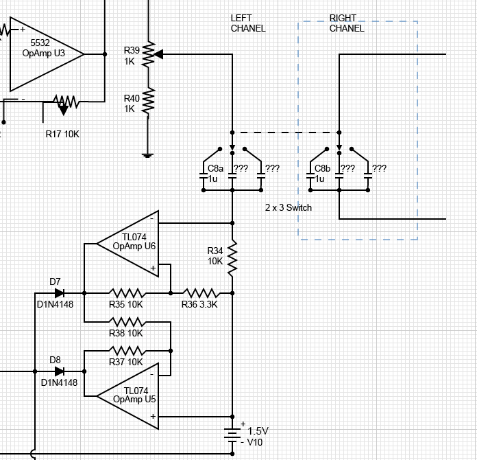
I'll update the schematic with stepped switches for attack / release based on Kents values.

I think R17 as a trim is a good idea as it allows you to fine tune the gain between the 2 channel and maybe compensate for tolerance in R39, especially if its dual. Sleeper said he used a trim on R17 cause he needed more gain due to his choice of interstage TX. I know it will make setting up more complicated, but is a trim on R17 a good idea or is it just overkill?

The meter section still sounds confusing, it may be better to leave that to individual settings or maybe completely loose the meter altogether and just use our ears... ;D

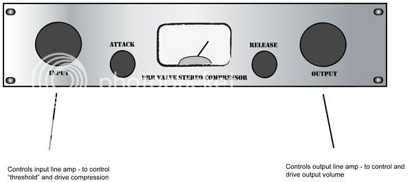
I was thinking of leaving R39 inside the case, and adjust compression with the input attenuator. That's why having enough input drive is important for me.

It sounds like the choice of iron play a major role in how this thing sounds. I guess now, for me anyway, my concern is which transformers to get.


Thanks for all your help.

J
 
Hi Ian, good to see you today!
Matthew here's a few corrections for you.
First, I'd do what the Bird says. especially with regards to the sidechain and that part where it feeds back into the grids.  I had thought about copying the center tap feed back as on the 175 but I didn't have a center tapped transformer AND I never got around to it AND I was happy with the 3.3ks as in the original PRR circuit.  

the attack release switching isn't right and neither was my explanation.  
the way I did it you do join the L and R sidechain where you have shown (just after the diodes)  this way the sidechains sum together so whichever side is loudest compresses both sides of the mix equally.  

you could go as far as having two sets of attack/release controls on the front panel, because this is what you are working with.  but to conserve panel space and setting headaches you use 2 pole switches with the stepped values as shown in the chart on Kents varimu PDF (or you can use any stepped attenuator calculator)
If you plan on using the unit for a lot of dual mono tracking it might not be such a bad idea to have two sets of controls, but you don't want these to be pots because you wont get good matching in stereo mode.
Kent has some other way of summing the sidechain but I didn't like it much.

Ian and I discussed it today and he used PRRs the meter section exactly as drawn with a 1ma meter and it worked.  
I used r3 at about 47ohms (not 330) and the 500ohm trimmer only with a 500ua meter.  I couldn't get a 1ma to move very much...   I also put in a switch so I could meter left, right, or summed.  the switching goes in between the center leg of the 500r trimpot and the meter.


I Made R17 variable in mine because it allows you to get a tighter left/right balance on the compression, you can make some minor adjustments and if you replaced tubes you could easily make some adjustments again... my R39 is front panel so it acts as a compression threshold control

good luck

OOPs I missed the send button and sat on this post for a few hours, meantime You replied, so If I reiterate something you already tackled that's why.
 
Just thought of something Regarding r17  If your opamp is socketed and you pull it out you can get an accurate measurement of trimpot R17 in circuit- so you can easily dial it to 2.2k while you are setting up.
 
Thanks guys....

Awesome!!!! This is the best forum on the net and I'm so glad to be a part of it....  :D

I'm gonna take my time and re-draw this schematic. I'll work on the attack/release switches using standard 1x12 switches such as the Lorlins.
For the sidechain filter, I was thinking of a 2x3 switch on the front panel that will switch the filter circuit on both L&R signals at the same time.

In the mean time, I'll welcome any more corrections or improvements...

A couple of questions... Is there an alternative to the 990?
What about a circuit based on the 5532?

Also how about op-amp balanced outputs instead of transformers? I was thinking of something like the output circuit of the GSSL. Would it work?

Personally, I'm gonna try this with OAP TXs to keep costs down. Anyone used them?

J
 
Hi Matthew,
almost anything that works  ;)
will work on the output.
Neve output driver and trafo on mine,
you could use an API2520, any one of the discrete amps here on the thread, yes 5532's, or a line driver like a drv134 . the bendo buffer used in the forssell opto comp sounds good driving just about any decent 600-600 transformer.

As long as the input impedance of your output stage is reasonable so it doesn't weirdly load up the interstage transformer or the sidechain you should be fine.

BTW My version doesn't have those 2k resistors that Bluebird's shows and everything behaves just fine here.
Kelly
 
bump for a great thread!

BTW Bluebird, do you or anybody else for that matter have those clips still that you posted of your unit in action??

Thanks

Peace
Illumination
 
Yo!!!!!

I've been really busy recently and haven't had time to finish the modified schematic.

I now need help with the filter capacitors values. Can someone help me with that?

I'm think switch:
position 1: full band
position 2: 90Hz lowcut
Position 3: 130HZ lowcut

These are the frequencies I have a feeling would be cool. I'm open to suggestions from someone with more production experience. What would be some good all round frequencies and what would the values of the caps need to be?

Thanks in advance

J

Picture1.png
 
Hi Matthew, once again I'll point you to a comparison.  I don't know, that's how I've learned things here so...
Anyhoo,
check out the ssl sidechain filter.  it has the frequencies that you want and MIGHT have the cap values you need BUT you have to be careful with how your cap values interact with R34, R36 etc. 

I say maybe because the filter as you have it drawn is not a totally straightforward RC type filter, it has complex moving parts like r39 and the virtual ground in that circuit and I'd need to do a fair amount of study myself to give you a straight answer.

Anyhow I know that's not so much help but it's a start.
Good luck with it.
Kelly
 
Hi Kelly

Thanks so much. I thought is was more complicated than that. I know a filter is a combination of a RC network and something to do with how easy certain frequencies make it across the caps or down to earth so the interaction with other components in a network is important.

I have a feeling R39 and R40 play a important role as well. R39 is variable so that should be interesting. If R39 is used as a threshold, changing the threshold will actually change the cut off point right? Do I have to use buffers to get around this challenge?

I'll have a look at other circuits, after all their is nothing new under the sun and isn't learning from others the basic essence of audio engineering?

I can also experiment once I get my unit built, but if anyone has already done this, I wouldn't mind their input.
Bluebird mentioned 0.0047uF for one of the values. This would be one of my starting points for experimenting.

Cheers

J
 
I don't know how the threshold trimmer would affect things, but if you look at your capacitors and r34 as your RC filter network (imagining that the virtual ground is, just ground) A value of .1uF would corner at 160hz and a .220uF would corner at about 75ish. This if just using this simple calculator:

http://www.muzique.com/schem/filter.htm

Nobody else was really chiming in on how and why to choose caps so I'm taking a stab (in the dark maybe).
 
Thanks for the link to the calculator. I'm gonna have a look at these frequencies tomorrow and probably finish the schematic tomorrow as well.

Illacov, have you got your board yet? have you started the project?

J
 
They were JUST shipped out last week or this week I believe. I don't know the turn around time, but I'm also in the USA so there's definitely a longer wait for me than you I'm thinking, since you're alot closer to Asia being in the UK.

I'm actually keeping track of all the cool ass mods in this thread that we're sorting out.

BTW just to add on:

Tom @ Cinemag mentioned that if the transformer you use for an interstage is reacting poorly to the DC it sees, that you can use a coupling or dc blocking capacitor to filter that DC out. I believe there's some information on it at Jensen's site on how to calculate what size cap you'd need. I'm remembering that you have to use a capacitor with a high enough capacitance so that your low end freq performance doesn't suffer, this is because the capacitor forms a high pass filter. I suppose if you get a cap that causes hpf around 5hz that it wouldn't be so bad of a loss since only elephants would complain but it wouldn't be a static loss so it might slope off later on as well, meaning if you get a cap in there that causes hpf at 20hz, you'll probably be losing a little bit of the later frequencies as well.

I am a complete fool when it comes to fully understanding all of this but google is your friend.

There's a formula on the web to find out what your coupling cap should be.

Just to reiterate, my planned TXs are CM1515B for input, CM9589L for interstage and CMOQ2S for output after the John Hardy 990.

And once again:

Anybody got some clips?

Peace
Illumination
 
Hi Gemini86

10uF.... hummm...

I checked the schematics of both the G9 & the PeQ that I have built/am building and Gyraf uses 4.7uf between the tube and the transformer on both models.

I guess space is a issue. Is it the higher the cap uF value the lower the cutoff point in Hz? In that case 10uF would be better right?

Space is not an issue as my transformers will be mounted off board.

J
 
yeah, the higher the cap the more bandpass, BUT the larger the cap the bigger it is, and you could get stuck using a 'lytic which most people don't like in their audio path.
 
Illacov,

Those transformers look good.

Nobodys going to need interstage capacitors. there shouldn't be a significant amount of dc. If there is its because one side of the tube is super weak or busted.

I would just like to remind people when I used the edcors in this project they didn't work well. The edcors really want to see the correct load and source. This circuit has a dynamic impedance on the plates.

One of the larger Edcors may be fine. they seem to work well in the Poormans 660. I just haven't tried them.

I don't have enough time to dig up the sound samples I made but believe me if you make this right it rocks. One of the best compressors I have.
 
Thanks Bluebird. I had already incorporated the interstage capacitors into the schematic I'm working on. I'll now get rid of them... :D :D

Thanks for the advise on the Edcor transformers. I know you have some vintage TX in your unit.
It would be nice if we can find a more "available" TX to make this mod more available to others. Maybe the Cinemag TX that Illicov got will work out well. Personally, although PRR designed this respectful circuit with simplicity and cost in mind, I think if with a little bit more investment and some modifications it can rival other vary-mu comps I think it still makes it a cheap and worthwhile project.

I am trying to consolidate all our ideas into a schematic. So far I have the sidechain filter idea, stereo link / mono, interchange TX, 990 output stage, stepped attack/release.

I would like to get rid of the threshold control. Instead I would set the threshold quite low internally with R39 on a trimmer for example. I would then control the amount of compression by driving the input (like a lot of UA comps - LA2A, 1173, LA4A, ect...). I would use the 990 for make up / output gain.

I am still trying to find a simple/cheap means to attenuate the input, bearing in mind that I want to attenuate a stereo balanced signal with one knob.

This is my simply front panel idea:
Front-Panel-idea.jpg


Let me know if yous got some more ideas on a stereo balanced input attenuator.

Many thanks

J
 
Sounds like a plan!

No threshold control would be more like a fairchild comp.

I know that if you want a colored sound, then that CM9589L from Cinemag is the ticket! It has a nickel/steel core and will give you a very nice fat sound! The CMOQ2S will have very nice layer of colored vibe being an all steel transformer. The nickel 1515B on the input will allow all those lovely transients to just right thru the unit with nothing veiled in the way.

Mix and match other transformers and you will change the unit!

On an added note:

The 600:600 Carnhills are being sent to testers. Pretty soon the 10K:10Ks will surface!

Imagine that! A NeveMu!! LOL

Peace
Illumination
 
Output Transformer question.

(Actually this is a "I'm not really sure I get this impedance thing")  ??? question. Notice on both the mods a 600:600 after the discrete opamp. I am assuming that the gain is such in the modified circuit to keep this in the -10dBv realm? or is it higher? (The ratio of resistors appears to be the same.) Also, what **is** the purpose of the output xformer in the mod? It isn't in the stock version. Is it to drive a balanced output?

Or can gain be adjusted by the pot/resister network about the 990?  Mr. Hardy's post suggest the gain is adjustable. I was wondering if it would be possible to set the gain at 20dB as in the original and then use  a 1:4 or 1:5 transformer to get to +4dBu assuming the input impedance was sufficiently high on the input device. (Again, I really don't get this impedance thing, my simple understanding has been input high good, output low good, drive low into high good, high into low bad...)

Now I have actually  perused many transformer threads here, and I think I understand the impedance ratios, but could use some clarification. It is my understanding that e.g. a 600:10k transformer isn't by itself 600 on one side and 10k on the other, but reflects the impedence on either side in a 1:4(sq) ratio. So if the impedence going in to this trafo was e.g. 47 ohms as in the circuit diagram it would show 47 ohms x 4 squared or about 752 ohms ont the other, which would be the nominal output impedance. (Which I understand would change too depending on the freq?)

Is this correct? With a similar ratio for whatever load impedance was on the 10k side?  

My goal (as soon as the next set of baords come) is to build the stock version, and then a 6ES8 version with the discrete opamp out. The PCB is fantastic, and looks like you can leave the PSU alone and just run 6v heaters in series!
 
Hi Blue Jinn

Sorry, I don't know much about impedance as well. It's one thing I simply can't get my head around, especially transformer impedance.

In this mod, by placing a transformer after the discrete opamp you effectively get a balanced output. It won't be exactly +4dB as the output level is affected by the potentiometer and resistor network around the 990. This is what will be the "output level" knob on the front panel of the PRR Comp. This should enable the unit to make up the gain lost in the compression process and should also enable the user to set the correct gain into the next unit in the signal chain (the audio interface or 2-track recorder or whatever). It should range from -inf to +28dB I guess.

We could replace this transformer with an IC output driver opamp, but the idea is to have a transformer there cause we like the sound of transformers and it keeps things simple as well.

The stock version is basically unbalanced. This mod makes this unit balanced and I'm sure the 990 can drive +4dB into a 600 Ohm load.

I'm thinking of putting an attenuator on the input of mine so as to have a +4dB balanced input as well.

I would like to build the stock version as well, but the cheap radioshack transformers that people used a few years ago are no longer manufactured to the same spec and are no longer applicable to this project. That is why I have decided to build this comp with the "bluebird" mod as I can use some "tried and tested" transformers that are sure to work.

However, there is still no confirmation on what would be good transformers. Bluebird says the Edcors are no good but maybe the big ones used in the PM660 will work. Illacov is gonna try some Cimemag TX. I hope he gets some good results with them.

Selecting the right transformers for this project is still whats confusing me.

J


Latest posts

Back
Top