You are using an out of date browser. It may not display this or other websites correctly.
You should upgrade or use an alternative browser.
You should upgrade or use an alternative browser.
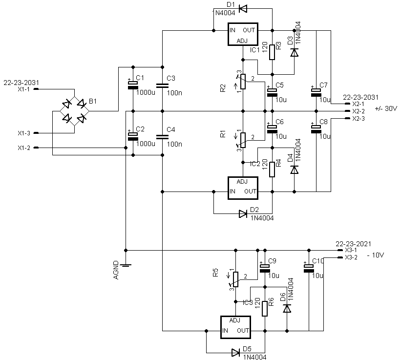
PSU for trafoless 1176 (Check my design,please)
- Thread starter ForthMonkey
- Start date


Help Support GroupDIY Audio Forum:
This site may earn a commission from merchant affiliate
links, including eBay, Amazon, and others.
ruffrecords
Well-known member
What software do you use to draw your schematics?
Cheers
Ian
Cheers
Ian
ForthMonkey
Well-known member
ruffrecords said:What software do you use to draw your schematics?
Cheers
Ian
I'm using Eagle.The easiest circuit drawing sofware to me.
Your circuit looks fine. But for the 1176 why do you need -30V? You only need +30V and -10V. And the -10V does not need high performance regulation or high current because it's just for the JFET bias voltage which is super low passed and draws almost no current and for the meter op amp which doesn't have significant demands. So the original zener shunt is quite appropriate actually.
ForthMonkey
Well-known member
ioplex said:Your circuit looks fine. But for the 1176 why do you need -30V? You only need +30V and -10V. And the -10V does not need high performance regulation or high current because it's just for the JFET bias voltage which is super low passed and draws almost no current and for the meter op amp which doesn't have significant demands. So the original zener shunt is quite appropriate actually.
Hi ioplex,
Thanks for info.But as i said i'm building trafoless 1176.Input circuit like LA4A.And again elec.balanced output.So i need +/- 30 for op amps.
Michael Tibes
Well-known member
Which opamps do you want to use? Most are +/- 18V afaik, the highest psu voltage I reacall from memory is +/- 22 or +/- 24V - unless you mean discrete ones?ForthMonkey said:...So i need +/- 30 for op amps.
Michael
ForthMonkey
Well-known member
Michael Tibes said:Which opamps do you want to use? Most are +/- 18V afaik, the highest psu voltage I reacall from memory is +/- 22 or +/- 24V - unless you mean discrete ones?ForthMonkey said:...So i need +/- 30 for op amps.
Michael
I will use NE5532.I believe it's OK to use them with 30V.Isn't it?
Andy Peters
Well-known member
ForthMonkey said:I will use NE5532.I believe it's OK to use them with 30V.Isn't it?
When in doubt, check the data sheet.
Even when not in doubt, check the data sheet.
-a
Definitely not ok. Absolute max is 44v total (+/-22). Safe is 36 (+/-18).ForthMonkey said:I will use NE5532.I believe it's OK to use them with 30V.Isn't it?
The balanced input circuit of the 1176 uses a single +30V supply with a 1/2 supply virtual ground to bias the + inputs of the op amps. R3 and R4 in the following 1176 schematic make the virtual ground:ForthMonkey said:But as i said i'm building trafoless 1176.Input circuit like LA4A.And again elec.balanced output.So i need +/- 30 for op amps.
http://www.gyraf.dk/gy_pd/1176/1176sch.gif
This is actually a perfectly good thing to do in this case because very little current is being drawn from the virtual ground.
Although this type of balanced input circuit is, in general, not that great. At least it certainly doesn't contribute to the character of the 1176. Just noise. A simple non-balanaced input would be better. Actually I would just ditch the op amp altogether since the input of the fet comes from a 10K pot which is a good input impedance.
If you must have a balanced input (because the input is connected by a longish cable in an electronically noisy environment), then a THAT1200 chip makes a better balanced line input. Although then you really would have to use a dual supply because it cannot use the virtual ground method.
Personally I would just use a transformer. A transformer is foolproof.
ForthMonkey
Well-known member
ioplex said:The balanced input circuit of the 1176 uses a single +30V supply with a 1/2 supply virtual ground to bias the + inputs of the op amps. R3 and R4 in the following 1176 schematic make the virtual ground:ForthMonkey said:But as i said i'm building trafoless 1176.Input circuit like LA4A.And again elec.balanced output.So i need +/- 30 for op amps.
http://www.gyraf.dk/gy_pd/1176/1176sch.gif
This is actually a perfectly good thing to do in this case because very little current is being drawn from the virtual ground.
Although this type of balanced input circuit is, in general, not that great. At least it certainly doesn't contribute to the character of the 1176. Just noise. A simple non-balanaced input would be better. Actually I would just ditch the op amp altogether since the input of the fet comes from a 10K pot which is a good input impedance.
If you must have a balanced input (because the input is connected by a longish cable in an electronically noisy environment), then a THAT1200 chip makes a better balanced line input. Although then you really would have to use a dual supply because it cannot use the virtual ground method.
Personally I would just use a transformer. A transformer is foolproof.
Thanks for explanation.
But for now building it with +/- 30 V is better for me.I will try elec. balanced input.If it's not worth it,i can use transformer.
I circuit to first post.
By the way which one is better?Using FDH333 or BF245 instead of it.
The noise level introduced by this type of input circuit is negligible compared to that of the 1176's gain-cell.ioplex said:Although this type of balanced input circuit is, in general, not that great. At least it certainly doesn't contribute to the character of the 1176. Just noise.
The disadvanyages of a non-balanced input generally outweight those of an electronically-balanced input. That's because hum and buzz are generally more intrusive than pure hiss.A simple non-balanaced input would be better.
A good quality transformer is, but many, due to economic reason, use cheap transformers that introduce BW limitations and distortions.Personally I would just use a transformer. A transformer is foolproof.
In terms of pure measurable and objective performance, nothing beats a well-designed EBIS, except for high-voltage isolation.
Michael Tibes
Well-known member
Putting things in context with your compressor: I don't know if it might be a good idea to run the output opamp on +30V with virtual earth, my gut says no. Then you'll anyway need 4 voltages in the psu: +30, +18, -10 and -18. I'd then also run the input opamp on +/-18V without virtual earth since you now already have these voltages and a stable ground is always best. Running it on +30V was a solution at UA to integrate the opamps into the original schematic without having to change the psu.
I don't know whether the original schematic with the 2 opamps in the input has any advantages over a simple one opamp solution which is often used nowadays? If not, you could change the circuit and drop one of these opamps. Now you would get away with one dual opamp chip for your purposes (one on the input and one on the output) for the audio path.
Hope this helps,
Michael
ForthMonkey
Well-known member
Thanks for ideas and helps to all.
I guess i find better way to do it without changing PSU.Another trafoless 1176 design uses original PSU.Added schematic to first post.
By the way i will use just one dual op amps for in&out but in Ltspice i can't use dual op amp.So i need to use dual single opamp.
I guess i find better way to do it without changing PSU.Another trafoless 1176 design uses original PSU.Added schematic to first post.
By the way i will use just one dual op amps for in&out but in Ltspice i can't use dual op amp.So i need to use dual single opamp.
Input circuit is ok, but output circuit is IMO one of the worst possible in practice.ForthMonkey said:Thanks for ideas and helps to all.
I guess i find better way to do it without changing PSU.Another trafoless 1176 design uses original PSU.Added schematic to first post.
By the way i will use just one dual op amps for in&out but in Ltspice i can't use dual op amp.So i need to use dual single opamp.
I would recommend either the cross-coupled circuit
See page 12 of http://www.hpl.hp.com/hpjournal/pdfs/IssuePDFs/1980-08.pdf for the original circuit designed at HP and later popularized for audio by MCI...
...or the much simpler impedance-balanced circuit.
The ultimate solution for electronically-balanced outputs is THAT 1646 but does not lenf itself to single-rail powering.
True. But for someone just experimenting with the 1176, using the 10k pot by itself as the input is not horrible. At least it will not load the source or filter or distort the signal.abbey road d enfer said:The noise level introduced by this type of input circuit is negligible compared to that of the 1176's gain-cell.ioplex said:Although this type of balanced input circuit is, in general, not that great. At least it certainly doesn't contribute to the character of the 1176. Just noise.The disadvanyages of a non-balanced input generally outweight those of an electronically-balanced input. That's because hum and buzz are generally more intrusive than pure hiss.A simple non-balanaced input would be better.
Actually if the source is known to be balanced (like the output transformer of a mic pre), then there would be no ground loop and thus no hum and the 10k pot by itself would actually perform better than a balanced input. Only one end needs to be balanced to break a ground loop.
ForthMonkey
Well-known member
abbey road d enfer said:Input circuit is ok, but output circuit is IMO one of the worst possible in practice.ForthMonkey said:Thanks for ideas and helps to all.
I guess i find better way to do it without changing PSU.Another trafoless 1176 design uses original PSU.Added schematic to first post.
By the way i will use just one dual op amps for in&out but in Ltspice i can't use dual op amp.So i need to use dual single opamp.
I would recommend either the cross-coupled circuit
See page 12 of http://www.hpl.hp.com/hpjournal/pdfs/IssuePDFs/1980-08.pdf for the original circuit designed at HP and later popularized for audio by MCI...
...or the much simpler impedance-balanced circuit.
The ultimate solution for electronically-balanced outputs is THAT 1646 but does not lenf itself to single-rail powering.
Thanks for advice.
Impedance balanced is best option,i guess.Cause i'm trying to build compressor with 1176 topology but cheapest and easiest one!
I'll add circuit with impedance balanced option.
ForthMonkey
Well-known member
I added impedance balanced version.What do you think?
you have added a voltage divider at the output (R56 & 57) that increases the output Z to about 2.5k; why?ForthMonkey said:I added impedance balanced version.What do you think?
As a result, one leg is 2575r and the other is 75r. Do you think it's really impedance-balanced?
ForthMonkey
Well-known member
abbey road d enfer said:you have added a voltage divider at the output (R56 & 57) that increases the output Z to about 2.5k; why?ForthMonkey said:I added impedance balanced version.What do you think?
As a result, one leg is 2575r and the other is 75r. Do you think it's really impedance-balanced?
Actually R56&R57 is ouput pot.I don't use pot simulation in Ltspice.
Adding resistors after pot is changing impedance?How can i make it impedance balanced after pot?
Similar threads
- Replies
- 26
- Views
- 1K
- Replies
- 3
- Views
- 302
- Replies
- 5
- Views
- 682