Pultec Inductors again...

GroupDIY Audio Forum

Help Support GroupDIY Audio Forum:

This site may earn a commission from merchant affiliate links, including eBay, Amazon, and others.
Older cores had a max Al value that left a lot to be desired.

I am sure the engineer today would use less turns on a higher Al core for a better "Q", or quality factor , which is the henries divided by the DCR.
Some meters have a D instead of Q, which is the same thing, only it is 1/Q.
So the higher the Q, the lower your D should be.

If you want old school, then use the original Al.

That way, you keep the turns the same, which means the flux is the same.

When you drop the turns, the flux goes up, because you are working the core harder in order to get more henries for the same price in turns.

So you may get a different sound with a high perm core.

Some of the new powdered cores have amazing Al numbers.

Remember that the thicker wire can mean more leakage C, since the "plates " of the capacitor are equal to the surface area of the wire, 2 pi r.

But you also get more space between turns, which decreases the leakage C.

Which one is worse is determined by bench testing.

You get a better Q because of the lower DCR, the tradeoff is more leakage.

Anything that uses iron is one huge list of off setting factors.


Hey pat, that #34, what did it mic out at?
Thanks!
 
Thanks Pat. :thumb:

Hopefully I got most of it right... but better you tell the story. :green:


You just can't go wrong with "Kashmir", mom's weed scale & Madonna in the same post.
 
Hello DIYers :grin: This is my first post on this forum and hope i will contribute efficiently to all your experiments as i learned from all of you :wink: I 'm very interested in inductive / passive corrections and one of my homeworks, at this moment , is passive biamping ... I use 3H1 ferrite cores with very good results , these come from old audio line eqs of the former ORTF , the french public broadcast television administration. I' ve been testing them with R&S LARU inductancemeter and B&K outputmeter . It seems that ferrite do not like high levels , or peaks . Accordingly , i try to maintain a max 0dB level ... I'll try to send pics hre if someone interested :cool: Pierre
 
Hi everybody,
i'm trying to upgrade my existing G-pultec,
i bought a Cinemag CML-150T inductor,
and was wondering if anybody has allready plugged this baby,
in a Gyraf Design Pultec ?
Hope somebody did,
Regards
Pacemaker
 
[quote author="pacemaker"]Hi everybody,
i'm trying to upgrade my existing G-pultec,
i bought a Cinemag CML-150T inductor,
and was wondering if anybody has allready plugged this baby,
in a Gyraf Design Pultec ?
Hope somebody did,
Regards
Pacemaker[/quote]

I posted about this in another thread... do a search!!!!

I found THIS right away:
How to improve the sound of my G-Pultec?

http://www.groupdiy.com/index.php?topic=29829

I posted what to do towards the end... page 1.
 
ok thanks Keith,
i allready saw this post
but as i'm using Gyraf PCB,
i just wanted to know
How to connect the inductor to the PCB,
not wich frequency or caps to choose,
but thank you again for answering ...
 
the Cinemag may have more taps [? ] than the gyraf board
can use BUT after looking at the cinemag website just choose
the cloest set of taps to substitute for the gyraf design
Or to be less confusing , you have to start on one wire to
call end or start winding [ top or bottom , hi or low ]
and sub the cinemag wires in sequence , whichever order
hi to lo , that corresponds with what the gyraf wants to see
in hi to low for inductor values , substitute

Since the inductor values may not be the same , the caps values
may need to change , but you can play with that later to taste
and if you give up something you may get Dr Pat's inductor from
the giveaway [ but you'll still have to install it ! ]
 
Strange,

When winding my toroid core,

do the 100 turns on the core to get the AL number, then

I calculate my turns number correctly using the N=100*sqr(L/AL) for all the turn numbers I need : 27, 33, 47, 68,82,150 mh

and I find that when I get to the final turn on each tap I make a inductance measurement and discover that the turns number is not exactly spot on.
in fact I have to either decrease or increase the number of turns a bit
to get the inductance (mH) spot on. I usually check the final result with a LCR meter to confirm. my meter gets me within .001uH of the correct inductance measurement.

Seems the mathmatical equation only gets me on a average within 10% of the correct mh number I'm shooting for. Which is probably Ok , I think .. but I ususally narrow that down even further with a wind adjustment and LC meter check.

I'm also finding that my DCR is off as much as 20% or more even when I have the correct inductance , but this could be due to my wire size and base core AL number. not sure though.

Question : Which is more important the (mh) number or the (DCR) number, and can DCR be compensated for in the circuit surrounding the inductor, since it acts as a resistor ?
 
+/- 1% tolerance should be acceptable :)

of course the inductance is more important than the dcr for our purposes - it forms the LC-filter´s frequency.

generally the DCR is not as important as many posts on this forum suggest.
more like a ballbark number.
 
My mistake,

I meant +/- 10% withing the desired inductance number in mH , not +/-1%
 
Pat, did you note the Start and Finish?
Sorry if it is in the thread already.

OK, if you want to match your Al number with something in a catalog, then the Industry Standard is done with 1000 turns, not 100.
And this makes a difference sometimes.
To see this, compute your Al number at both 100 and 1000t, or whatever turn number/tap is close to 1000.

The first turns have to eat the core loss, which is pretty low in a good powder core, compared to a laminated choke for instance.

So as you add turns, you get more inductance per turn.
That is why you sometimes need less turns than calculated.
Also, you get better coupling as you get more tuns on there, which means less loss.
But then you gotta worry about the DCR a bit as you near the finish.
This may eat into the inductance per turn ratio, thus making you wind more turns to get at your final tap.
But DCR is at a 90 degree angle to the reactance, so it does not really enter into the equation.
And now, since your wire might be further from the core, you get less coupling.

So you have all these variables that roller coaster back and forth.

Plus, each LCR meter checks the inductance at say, 1000 hz, and at a pretty low level.

That is fine, as long as your inductor will only be used at, 1000 hz at a pretty low level.
Your inductor could measure fine on a meter, but crap out at either the high or low end, and you would not know it.
Could be winding technique or core problems that do not show up on a meter.
Your EQ seems less effective on certain bands than the stock model.
Which is, a bummer.
But I like the Bass bands, do not tell anybody, but I rarely use the Bell Curves.
Only the shelves.
Unless the mix is real messed up.

So sweep your inductor with the cap it will be teamed up with on a bench, if you can, and do a freq plot of the Bell Curve.
Use a Resistor in Series with the inductor tap and cap, which is also in Series.
Keep track of the input signal, as the circuit will eat different amounts of power, depending on the frequency.
Use just enuff resistor to get off the noise floor of the scope leads.


Inductance figures are just to get you in the ball park, then, like the guys said, you tweak the bands with the cap.
 
All good info. :thumb:

I followed the math that Pat posted & it got me almost dead on... the frequencies looked pretty good too when matched with the original cap values.
BUT... a lot of my "Lower" bands were slightly off (they would be at the END of the wound taps = higher turns or inductance for the lower bands)

They looked good on my meter but needed a slight cap adjustment to center them up. :wink:

Yes, a LOT of variables but if you get close you will STILL have a nice, working inductor. I have 3 Stereo units & EACH one uses different Type & Style inductors = Ferrite, pot core & powder-core... They are ALL cool.

The inductance I measured with my LCR worked when I put the #'s in the "On-Line" Calculator I posted earlier... My inductance reading + the Cap value it gave me matched the frequencies when I "Swept" my unit.
 
Also, the cap that is in series will have a 20 percent tolerance, and will change with the weather, thats if you use the old funky wax coated paper stuff that gets ripped from 50's hammie chassis.
 
Ioaudio
Dr Pat
Khstudio
CJ

Thanks for the replies. This continued discussion is one of the best and certainly most interesting topics I've worked with here on the forum. and I can't say enough how cool it is to have you guys around to talk with. I don't think I even got this stuff in college like its being discussed here. :thumb:

Khsudio, the online calculator works great in tuning the correct cap with the inductor tap value !!!
http://www.elec-toolbox.com/calculators/cfl.htm

I have a 120hz, 1khz, 10khz option on my LCR meter to test inductance. Its evident, when I use these, the inductance varies a few mH's up or down as CJ suggests. I have not done a sweep yet but what would be the low and high end suggested for the sweep frequencies. I'm guessing at 40hz - 50khz and plot

Surprise, I thought the 100 turn AL value was suggested in a previous post(probably close enough) . Looks like 1000 turns is even more accurate. Its difficult to wind 1000 turns on a toroid by hand just to get the AL value. I have something like 15 cores that I have gone thru and found one that was worthy for use in a pultec and I have seven of them that are waiting to be birthed. I've been using the ten turn measurement as a fast check to get to the suggested pultec core value. So far it works according to what I have gathered so far. I'm getting around 12uH on ten turns and between 680 - 876uH for 100 turns with 33AWG wire. I have to change my wire to #34AWG , but with a difference of 1 AWG I thought it would give me results that are close enough for prototyping purposes.


Since its suggested that 12-16uh for a 10 turn and a 876uH for 100 turns is a recomended for a pultec core , then what about 1000 turns .....

Is there a AL value on a pultec like core with 1000 turns ?

Even better is there a formula to wind the core with "x" turns and "x"AWG to determine the final outcome of the AL number using a matrix lookup chart ? so as to avoid a lot of un-needed winding to get the same information.

Strange , I noticed that cores have little or no markings to identify them.

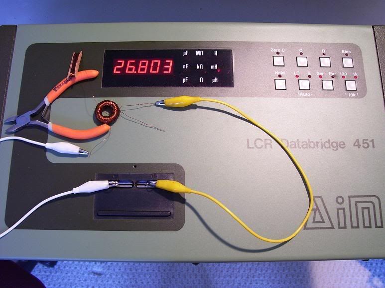
Below is a pic of the first tap tested with 10khz test signal, approx 630 turns.


27mH_1.jpg
 
Since its suggested that 12-16uh for a 10 turn and a 876uH for 100 turns is a recomended for a pultec core , then what about 1000 turns .....

We are lucky enough to have Pats DATA... at this point, it's the closest to original I think your gonna find unless someone rips apart a REAL Pultec to do it. 100 turns worked out great for me.

If you're getting "close" to the 876uH #... then I'd say your there. :green:

BTW... that's a damn nice LCR you've got there. :shock:

I used a basic ($180 Hand Held) LCR & it worked for me... it's obvious that the measurements I got using my LCR & the online calculator gave me the frequencies I wanted after sweeping my Pultecs.

I think what CJ said about the "Variables" did mess with me a bit towards the second half of the winding process... but not enough that I couldn't adjust the caps ... just a nano nut. :wink:


I have a question for you :idea:

Have you built &/or listed to a Pultec (or passive EQ) yet?

If so... have you tried or listened to different inductors yet???

If not... you need to. You'll get a MUCH better understanding after "Hearing" them for yourself... trust me. :wink:

It looks like you're about there with the inductor thing... I'd get building & start listening if I were you.

Good luck man.
 
I have a question for you

1.Have you built &/or listed to a Pultec (or passive EQ) yet?

2. If so... have you tried or listened to different inductors yet???

3.If not... you need to. You'll get a MUCH better understanding after "Hearing" them for yourself... trust me.

4. It looks like you're about there with the inductor thing... I'd get building & start listening if I were you.

1. It's First time building a pultec, have never heard one in a studio enviroment, but that will change soon enough. :roll:

2. Have'nt auditioned different inductors yet, hoping to do so ...

3. I fully agree, can't wait to further the listening experiments....

4. Definitely Kevin, I'm nearing the end of my BOM with the pultec parts.
cant wait to start building and experimenting :thumb:
 
[quote author="khstudio"]We are lucky enough to have Pats DATA... at this point, it's the closest to original I think your gonna find unless someone rips apart a REAL Pultec to do it.[/quote]

I hope everybody understands by now, that I DID rip apart a real Pultec to do this.

It was a huge undertaking, and the EQ stayed in that state for a couple of weeks, till I wound an inductor that sounded like the original.
 
Back
Top