quad eight mic pre [pics]

GroupDIY Audio Forum

Help Support GroupDIY Audio Forum:

This site may earn a commission from merchant affiliate links, including eBay, Amazon, and others.
EDIT: I figured out what I did wrong. I forgot to strap 5 & 6 together on the card connector. Damn... these things are sweet!
 
Well Guys,

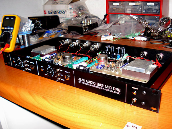
It finally got around to racking my Quad Eights up!

Quad_Eight_Front_Alt.jpg


Quad_Eight_Insides.jpg


It was a pretty painless exercise and based on the info loosely floating around I just approached it as an AM-10 with a input/output transformer, which essentially it is.

I removed the 4.7uF cap and jumper and decided to mount the input transformer onboard, the way the CA-227 was originally intended to have. I believe that Orphan have a Zobel but I didn't add one and according to Cinemag it isn't needed, someone had already replaced the resistor on the trano secondary with a 360K, which works well.

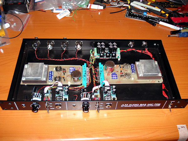
I wired it 150 on input and used the JLM Go Between kits and Joe's new FET DI and a AC/DC power supply. I had a spare Animal Pre case (I had a few of these made for racking Animal Pres) which it all got racked in, but at some point I'll get a little name plate stating it is a Quad Eight.

Harpo helped out with a spreadsheet to work out the gain steps using a rotary switch and it works like a charm. I added a 470uF cap in series with the resistors to smooth out any pops/click while changing gain settings and all is well, silent/click less gain adjustments.

Thanks again to all who contributed in this thread and the many others.

Loving the pres and hope to get them in my rack ASAP.

Cheers

Matt
 
Matt - looking awesome as always (the rack, not you!).

I need to see stuff like this now and again to inspire me to get building more.
 
[quote author="rodabod"]Matt - looking awesome as always (the rack, not you!).

I need to see stuff like this now and again to inspire me to get building more.[/quote]

GEEZ! Talk about calling the kettle black you burly Scotsman, Hah Hah!

Yeah, my own personal DIY has taken a bit of a back seat and it felt GREAT to be ordered enough to site down and just DO IT!

I'm also working on my G9. I got the boards a year ago from Steve at the Duke DIY Drinks Night... taken a YEAR to get done and that will prob be my DIY quota for the year :roll:

Matt
 
[quote author="MikoKensington"]Nice work! Glad they went to good use. I knew you'd do them right. :thumb: :guinness:[/quote]

Thanks Miko :thumb:

I'm glad I bought em, even if they took a while to get to, LOL. Looking forward to using them on upcoming sessions.

Cheers

Matt
 
[quote author="CJ"]Miko, i just had a seizure.

your shit is the bomb, bi-atch![/quote]

Hey CJ,

Sorry to read of your seizure :shock: I hope you are making a full recovery.

Not sure if you commenting on my rack job or not, but I took a feather from your cap and decided to mount the trafo's onboard. No nest of cables picking up radio stations and keeps the job looking neat as well.

Out of interest why do manufactures sometimes have a separate wire for the transformer core and separate one for the shield/can? Why would you want to ground one and not the other?

Take care :thumb:

Matt
 
why are you murdering Richie Zambora?

What are some of the things he did to you?

I'm not at liberty to discuss this until my lawyers have looked over the contracts... something about a Flying V, a music video and a Fender no no...

Matt
 
Stupid question time (which I am almost certain I've asked before but cannot find):  To bypass the 4.7uf cap, I can just jumper that baby, correct?
 
I am racking up a pair of the 137 cards and using JLM Go Between Plus and AC/DC PSU. In reading the schematic, I just wanted to verify that on the amp card:

Pin 1 = V+
Pin 2 = V-
Pin 3 = ground

Also, with respect to pins 9 & 10 bring wired to a gain pot, which pin goes to which leg on the pot?
 
I've got a pair of 127a to rack still..  Do you have an actual schematic for your 137s?  I'd love to see it.

Power is as you put it, according to the Q8 schems I've seen.

As for the gain pot, Pin 9 is ground, pin 10 is the inverting input of the opamp.  The pot is wired like in an API.  Use pins 2 and 3 of reverse log pot, shouldn't matter which pin goes to ground and which to the inverting input, it's just a variable resistor.  Max resistance when it's counterclockwise (min gain), and minimum resistance (max gain) when fully clockwise.  You probably want to add a resistor in series with the pot to limit your max gain. 
 

Latest posts

Back
Top