Any thoughts on the bar graph frying things?
You are using an out of date browser. It may not display this or other websites correctly.
You should upgrade or use an alternative browser.
You should upgrade or use an alternative browser.
SB4000 Support Thread
- Thread starter ruckus328
- Start date


Help Support GroupDIY Audio Forum:
This site may earn a commission from merchant affiliate
links, including eBay, Amazon, and others.
0dbfs
Well-known member
If you hook it up backwards it doesn't work. Just reverse the leads. I hooked up a couple of the led's backwards with no ill effects. Except it didn't work. Swapping it around fixed the issue for me every time.
Not sure if this is true for the bargraph led display. I've got one that does not display any activity with signal present. The other is fine. Have not investigated yet but now I am thinking that if the regular led's have A/K the the the led bargraph display prolly does too.
Cheers,
j
EDIT:
Yep. It was backwards or upside down and it didn't fry. Works great now! I may try to calibrate it down a bit so I get more headroom on it. Need to grab my rms meter from work. Two units done! Thanks Ruckus & Ptown! These are pretty sweet kit. Will definitely take my mixes to a "new-level". Cheers, jobu
Songguy
Well-known member
Hey mike,
Sidechain xlr wiring question.
xlr: which pin goes to Send, which pin goes to RTN.
Thanks,
C
Sidechain xlr wiring question.
xlr: which pin goes to Send, which pin goes to RTN.
Thanks,
C
ruckus328
Well-known member
sr1200 said:Any thoughts on the bar graph frying things?
1) Is it wired correctly?
2) Is the LM3916 on the control board in the correct orientation?
Otherwise, disconnect and check if you have any DC voltage on the center pin of the bargraph connector on the main board (with a test tone signal present of course.) Level of DC will vary depending on how loud of a test signal you're sending to the unit.
If you do have a signal, your problem is on the control board, if you don't, then the problem lies somewhere in the VU Driver Circuit area.
ruckus328
Well-known member
Songguy said:Hey mike,
Sidechain xlr wiring question.
xlr: which pin goes to Send, which pin goes to RTN.
Thanks,
C
It's an unbalanced signal, it should be wired whatever way works for your system to get it to and/or from whatever you'll be hooking it up to. XLR is for balanced signal, so if you use an XLR for both Send and Return, you'll need a "Y" Cable to break the signals back out to two 1/4" TS's. Most practical way to wire it all up though (what I would do) is tie both sends together and connect to XLR Pin 2 or 3, tie both returns together and tie that to XLR Pin 2 or 3. XLR pin 1 always to ground (well, or sometimes ungrounded, but I mean its never used to carry a signal).
Get a "Y" cable (XLR to dual TS) and just leave it permanently connected to the XLR. Now you have a mono send and mono return connection (You'll probably never use the send). But "return" can be used to trigger compressor from external mono source (ie kick drum, etc).
As far as I can tell, its hooked up exactly like my working unit1) Is it wired correctly?
its good2) Is the LM3916 on the control board in the correct orientation?
I will try this once i get home. I should note that with me pulling the thing in and out of the case, the 150ohm TO looking resistor near the bargraph disintegrated (literally crumbled and the leads came out of the black part with almost NO force. (ive had legs fall off regular resistors, but nothin like that lol) I ordered a new one and am waiting for it to come (hopefully today)Otherwise, disconnect and check if you have any DC voltage on the center pin of the bargraph connector on the main board (with a test tone signal present of course.) Level of DC will vary depending on how loud of a test signal you're sending to the unit.
If you do have a signal, your problem is on the control board, if you don't, then the problem lies somewhere in the VU Driver Circuit area.


![Soldering Iron Kit, 120W LED Digital Advanced Solder Iron Soldering Gun kit, 110V Welding Tools, Smart Temperature Control [356℉-932℉], Extra 5pcs Tips, Auto Sleep, Temp Calibration, Orange](https://m.media-amazon.com/images/I/51sFKu9SdeL._SL500_.jpg)


Alrighty, i replaced my blown parts and fired up the unit... NO FIRES! NO EXPLOSIONS! NO AUDIO! 
It passes audio fine in bypass but is dead when engaged. Im poking around looking for something but what i dont know. On top of this thing not working, my scope just crapped out on my (has been a great day lol)
In comparing voltages around the units (from the working one to the non working one)
the first point i tested was RW and R0... the working one i have almost nothing like 6mv (and i have a crappy meter) the non working one i have like -14V (something is a miss right here) The LW and L0 are the same on both units. (cap replacement time i guess) any thoughts on this?
minor_glitch
Well-known member
Hey everyone,
I've been taking lots of photos of my build and I thought I'd share them with you.
I considered waiting until the unit was up and running before posting the links, just to save embarrassment if it doesn't work, but what the hell.
Keep in mind, I'm somewhat a newbie. I've only built a VP26 and Bo Hansen DI, along with a couple simple mic mods and a failed attempt at a DOA. So if you enjoy photos of questionable soldering and how NOT to do things, see below:
http://paulmantiniaudio.blogspot.com/2011/06/sb4000-build-part-1.html
http://paulmantiniaudio.blogspot.com/2011/06/sb4000-build-part-2.html
http://paulmantiniaudio.blogspot.com/2011/06/sb4000-build-part-3.html
Harpo
Well-known member
Confirm, JMP6 and/or JMP9 isn't mistakenly populated and all +12V, +15V, -12V, -15V supply voltages are operating.sr1200 said:...the first point i tested was RW and R0... the working one i have almost nothing like 6mv (and i have a crappy meter) the non working one i have like -14V (something is a miss right here) The LW and L0 are the same on both units. (cap replacement time i guess) any thoughts on this?
Power down, temporary pull out U17 (the right-CH audio-VCA) and link VCA-in/VCA-out (pins 1/8 for THAT 218x) with a piece of wire and power up again.
U17 pin 3 or U18 pin 6 should read the same control voltage as U11 pin 3 or U12 pin 6, else correct the wrong resistor values R121, R126, R125, remove the short at U17 and/or U18 (a magnifying glass might help to spot it) or replace the broken NE5534 U18.
Confirm, audio is working on both channels, right channel with temporary bypassed VCA obviously without compression, and RO and/or RW (they are the same) doesn't give you this -14VDC readout.
If RO and/or RW previously gave a -14VDC readout, the 100uF C32 as well as the 22uF C96 might be blown from reverse biasing.
If all is behaving well and nothing was to fix up to now, expect the VCA U17 to be blown, else power down, replace the temporary wire link with your pulled VCA and measure again. You might confirm your VCA maybe broken by swapping with a VCA from a working unit.
With signal present, your VU-meter now should be working again in all modes (default setting is sensing the -now fixed- right channel output), else check U14-pin 1 for same level as U3-pin 6 or U5-pin 6. Case not, C96 and/or U14 seems blown.
...just some hopefully useful ideas to fix it.
;D wow thanks for the help. Ill try all this tonight. I did have a blown cap (one of the 100uf's) replaced it but it didnt help.
EDIT: I just noticed on my working unit that jmp1 and 4 arent populated (unless i did it on the bottom of the board which would be weird)
EDIT: I just noticed on my working unit that jmp1 and 4 arent populated (unless i did it on the bottom of the board which would be weird)
Harpo
Well-known member
You might have blown C32 again, if you didn't fix this -14VDC issue before repopulating this cap.sr1200 said:I did have a blown cap (one of the 100uf's) replaced it but it didnt help.
Seems right for a THAT2180. You never told us, what VCAs you are using.I just noticed on my working unit that jmp1 and 4 arent populated (unless i did it on the bottom of the board which would be weird)
Using the kit from Ptown. (so yes THAT chips)
K so following the suggestions above, i jumped the THATS and the voltage problem went away. (only 1 of them seems to be bad though)
Unfortunately, i think the caps did blow again, as im getting really odd voltages on the caps in comparison to the working unit. I think im just gonna shelf this until next week. I ordered replacement chips and caps for the input section, the vca section bar graph section and side chain section. Once i replace all the nasties, i think ill try again. Thanks for the suggestions
Unfortunately, i think the caps did blow again, as im getting really odd voltages on the caps in comparison to the working unit. I think im just gonna shelf this until next week. I ordered replacement chips and caps for the input section, the vca section bar graph section and side chain section. Once i replace all the nasties, i think ill try again. Thanks for the suggestions
Harpo
Well-known member
Using the kit from Ptown. (so yes THAT chips)[/quote]sr1200] [quote author=Harpo said:You might have blown C32 again, if you didn't fix this -14VDC issue before repopulating this cap.sr1200 said:I did have a blown cap (one of the 100uf's) replaced it but it didnt help.
Seems right for a THAT2180. You never told us, what VCAs you are using.I just noticed on my working unit that jmp1 and 4 arent populated (unless i did it on the bottom of the board which would be weird)
??? You could have been a little more specific. AFAIK Ptownkit kits come with 2x THAT 2181A for the audio chain and 1x THAT 2181C for the side chain, and if these are the types of VCA you have populated, JMP1 and JMP4 should be polulated and R76 and R96 are 680K resistors.
[quote author=sr1200]K so following the suggestions above, i jumped the THATS ...[/quote]
THATS implies plural. I was talking U17, not U11 and/or U10.
You already confirmed the next fixing step 'U17 pin 3 or U18 pin 6 should read the same control voltage as U11 pin 3 or U12 pin 6, else correct the wrong resistor values R121, R126, R125, remove the short at U17 and/or U18 (a magnifying glass might help to spot it) or replace the broken NE5534 U18.' ?, else you might fry your replacement VCA again from exceeding parts max.allowed Ec+/Ec- control voltage of +/-1V. Expected range is in between 0V (no compression/bypass) and about +/-0.12V (max.compression/makeup gain), else there is something wrong in your sidechain section as well.
sorry, Ill try to be more specific. :-[
I jumped U11 and U17 - got correct voltages and the -14v went away at rw/r0.
I discovered that the 2181A i had in U17 was indeed blown. It does look as though C32 is shot (open)
The resistors at 76 and 96 are 680K
i completely re-soldered the board looking for shorts and cold solders... didn't find any. I think this is just fall out from me placing U18 backwards on my initial power up.
R121, 125 and 126 are all correct values (though when measured 121 and 77 both seemed to be low (but it read exactly the same as on my working unit)
All power rails are working just fine.
My working unit has the same kit as the non-working unit(as in same VCA etc.) and jmp 1 and 4 are NOT populated yet it works fine...
I should be getting my replacement parts either tonight or tomorrow. Ill check back after ive repopulated the broken components.
ruckus328
Well-known member
meh, disregard, missed your first sentence.
Wow!
Got it done finially, just adjusted everything. Played some mixes through it - man, I am going to need to spend some time with this thing! I really took the ugly edge off, rounded out the sound. Now I understand what you mean by Glue. I also tried it on a drum buss and some vox. Man, it really made everything sound better. Bad part is - I now have to go back and remix all these songs I thought I had finally finished recently. They ain't done yet!
Lot of work, soldering, reading datasheets, but it was fun. I have to say - the board is really nice, so easy to solder on. The way it is set up so all the polorized caps only go one way and other small touches really made this a great project. The parts kit was excellent also.
I just wanted to say - great job guys. Great kit and it really was worth all the effort.
Thank you!
sheadstedford
Well-known member
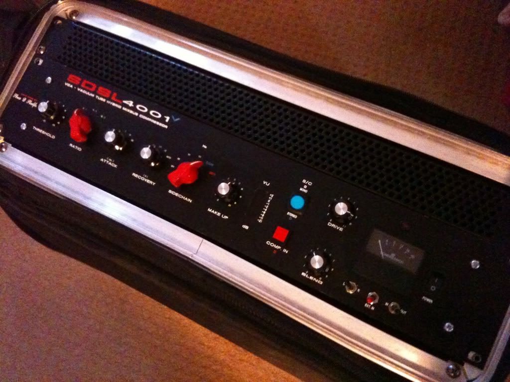
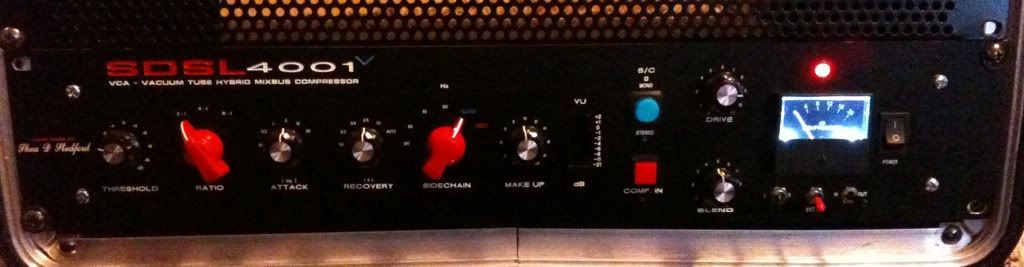
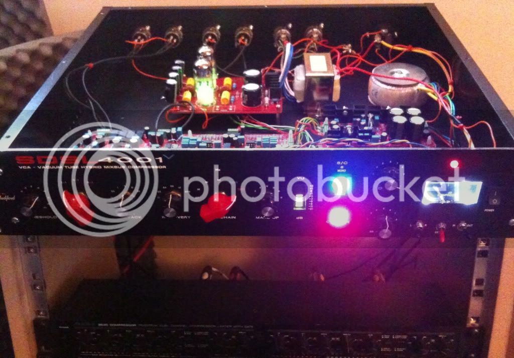
Finally completed it!
Tube drive stage and
VCA symmetry control modifications.
Love it!
Lets hope the marks reflect the work!
Thanks again rukus and ptown for making it possible
And the 3630 sits below looking above at its God..... lol
Similar threads
- Replies
- 0
- Views
- 1K
- Replies
- 98
- Views
- 15K