SB4000 Support Thread

GroupDIY Audio Forum

Help Support GroupDIY Audio Forum:

This site may earn a commission from merchant affiliate links, including eBay, Amazon, and others.
My first post, so go easy on me.  ;)

I've ordered my front panel and circuit board. I was looking at ordering all the components as per the BoM.

There are some capacitors listed in the BoM that are unavailable from Mouser, that I need a little help with equivelents.

495-1092-ND  CAP, 0.0015uF, 50V, 5%, METALLIZED POLYESTER FILM
495-1095-ND  CAP, 0.0047uF, 50V, 5%, METALLIZED POLYESTER FILM
495-1098-ND  CAP, 0.015uF, 50V, 5%, METALLIZED POLYESTER FILM
495-1099-ND  CAP, 0.022uF, 50V, 5%, METALLIZED POLYESTER FILM
495-1101-ND  CAP, 0.047uF, 50V, 5%, METALLIZED POLYESTER FILM
495-1102-ND  CAP, 0.068uF, 50V, 5%, METALLIZED POLYESTER FILM
495-1105-ND  CAP, 0.15uF, 50V, 5%, METALLIZED POLYESTER FILM
495-2522-2-ND  CAP, 220nF, 50V, 5%, METALLIZED POLYESTER FILM
BC1054CT-ND  CAP, 10pF, 100V, 5%, CERAMIC, C0G RADIAL
BC1055CT-ND  CAP, 22pF, 100V, 5%, CERAMIC, C0G RADIAL
495-3303-1-ND  CAP, 33pF, 100V, 5%, CERAMIC, C0G RADIAL
BC1057CT-ND  CAP, 100pF, 100V, 5%, CERAMIC, C0G RADIAL

I noticed that these are all EPCOS series B32529.

However:

P4525-ND  CAP, 0.1uF, 50V, 5%, METALLIZED POLYESTER FILM

Is Panasonic series ECQV(L)/(M).

Can I substitute all the capacitors to the Panasonic type?

I am based in the UK just in case anyone can advise of any other suppliers.
 
Is there a specific way the pots have to be soldered in, as in angle or the way the pins line up, or are they functioning rotary style with all those resistors around them? what parts should be left out? it seems like there are a lot of extra modification options in this kit. what transformers (power,input,and output) should i order? i want ones that are closest to the original, but also money is an issue. they need to be cheap. what is the cheapest chassis for this? I dont understand how to read the trimmer resistor values on these small blue trimmers from ptownkid's kit.

also, what does jmp 7 do? should it be used for the standard build?

Sorry, im new to all of this. There is only way to step my game up... and that's to go for it.
 
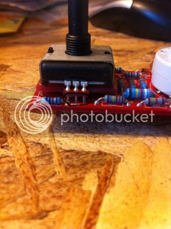
should these 3 pins be soldered in (the ones that are lined up coming off of the bourns switch), or do the connections not have to be in parallel with the 3 connections that I made with the old diode clippings that come out of the extra PCB's that it instructs you to use in the build manual. Am I making sense? That might be stated in a very confusing manner but I think it delivers my question.

My concern is if the circled leads should be clipped or soldered.


d75cdf9f-1.jpg
 
You can do either clip or solder, it doesn't matter.

Electrically they are still connected due to the daughter board.
However every bit of mechanical strength helps, since this daughter board is the only mechanical connection between this floating switch and the board, so, to increase strength, I soldered it in.  Your mileage will vary, but I was lucky enough that the tabs on the outer also fit through the holes on the board JUST enough for me to be able to solder them to the top track of the board, so I did that also.  It just makes the whole thing stronger and more resiliant to being thrown at people, which you may or may not need to do....
 
etheory said:
You can do either clip or solder, it doesn't matter.

Electrically they are still connected due to the daughter board.
However every bit of mechanical strength helps, since this daughter board is the only mechanical connection between this floating switch and the board, so, to increase strength, I soldered it in.  Your mileage will vary, but I was lucky enough that the tabs on the outer also fit through the holes on the board JUST enough for me to be able to solder them to the top track of the board, so I did that also.  It just makes the whole thing stronger and more resiliant to being thrown at people, which you may or may not need to do....

I had assumed that but didnt want to move forward in case of some kind of weird technicality. Thanks, I appreciate it.
 
The adapter boards were because I was originally using Honeywell Pots which have short leads, so needed some way to compensate.  I haven't used the bourns pots, but from the looks of the pics the adapter boards might not really even be necessary if the bourns leads are long enough to reach the control board, but no harm if used either.
 
Quick question, at the outputs of the small power conditioning board I am getting the specified voltages within a +- 2% range.  Is this a good enough tolerance for voltages in this application or does something need fixing?  Read through the thread but didn't see anything.  Maybe the answer will help the next person.  Thanks.
 
When you consider that resistors are generally +-1% ( to +-5% ), capacitors as much as +-25%, and various transistor parameters are even worse, and all of these figures get even WORSE across varying temperature ranges, etc. etc. it's amazing that ANYTHING analog EVER works.

+-2% total discrepancy across ANY entire working circuit is EXTREMELY good.  However, if like me you lust after every last %, replace the resistors with trimmers ( preferably 25 turn ones if you are super anal ) and trim the values as close as you want to within the tolerance of your multimeter.  This won't help much though, when you consider it's got about a +-1% tolerance anyway ;-)

Sorry, I tend to digress.  Yes, that's perfectly fine ( in fact it's better than mine was.... )
 
Good point.  Actually I read your blog (extremely nice job all around by the way, and I think I am going to copy your hot glue gun idea) and for some reason I thought *your* voltages were spot on right out of the gate, so then I started to wonder... 

By the way, wish I had someone like Talsit around here.  Hope you bought him a beer or something along those lines.  And now I'm digressing...:)
 
I'd like to second Shy's question. Can the polyester caps be the panasonic type? For example I just realized that all of the .1uf poly caps I ordered were the panasonic type. Any help would be much appreciated.
 
ruckus328 said:
bmaughan said:
hey, i was wondering if anyone either knows where to find or something that can subsitute for the B32529C152J's (C28,C31,C36,C41) in the circuit...will any 1.5uf  63v polyester work?
Did anyone else have any issues tracking this part down?....no one has it

any 1.5nF polyester, 50V or higher, .2" (5mm) lead spacing will work fine.  Just make sure the physical dimensions aren't so big that it doesn't fit in the board.  The same applies to any of the other film caps.

Was answered on previous page.
 
Hi Folks!

I was wondering that www.diypartssupply.com don't sell the SB4000 - Kit no more. Unfortunately they don't answer my question. Did I miss something or where I can find that stuff to order?

Thanks!

Kind regards
 
adrenalin1982 said:
Hi Folks!

I was wondering that www.diypartssupply.com don't sell the SB4000 - Kit no more. Unfortunately they don't answer my question. Did I miss something or where I can find that stuff to order?

Thanks!

Kind regards

Hey,

Download Build Manual (UPDATED 2/28/2011): on the first page-->

I got my Bom list from mouser and Farnell... I didn't find some parts on mouser so I had second list from Farnell!
Firts Link : https://fr.mouser.com/ProjectManager/ProjectDetail.aspx?AccessID=cd136fe51b
second link is my gmail account link, you will see just parts number ! you need to copy- paste! Just Attention for second link because I had some resistor for my other project!!!!
https://docs.google.com/viewer?a=v&pid=explorer&chrome=true&srcid=0B0nKUsFBLtnPMmFmZmExMmYtYzI0OC00NTM1LWExYjktZGI0N2NjODFlM2M4&hl=en_US
 
Hi everyone - I'm loving using my sb4000!!  But, when I try and get more than 5dB compression in either 4:1 or 10:1 mode or over 10dB of compression in 2:1 mode the needle jumps around like crazy and makes a sucking sound.  The best way to describe it is the sound of a transient triggers the compressor and it clamps down severely (as in the audio completely disappears, very extreme) and then slowly releases (even if I have a slow release time selected). 

I'm wondering, would the 47K resistor fix this?  Or is there a wiring error somewhere (the unit seems to works great on lower levels of compression).  (I did double check the value of all caps and resistors when I installed them) Also, the compression calibration procedure worked flawlessly, so makes me think it's not a wiring error??  Is there a detector circuit, because some time the "whooshing" triggers at low audio input levels when there is not even any big transients.  (like a high hat/acoustic guitar intro to a song)

any thoughts would be greatly appreciated!!!  I might try and put the 47k in today just to see if it helps things.

best,
Greg
 
Strange, first time hearing an issue like this.  There is an error somewhere, but this has nothing to do wih the 47K resistor.  Could be alot of things, but my first suspect would be dodgy +/-12V control voltage.  Check and make sure you have proper +/-12V on the main board.  Check voltage on the pins of your threshold pot on the control board (you should have +12V on the CCW pin and -12V on the CW pin), to make sure you have propper +/-12V on the control board.  Buzz out your ribbon cable and make sure you have continuity to rule out a potential bad connection.

Also, run a mono signal just on the left channel and see if you still have this problem.  Then repeat for the right channel.  This will help narrow down if it is an issue in one of the channel's ratio/feedback networks or if it is happening after the summing point.
 

Latest posts

Back
Top