SB4000 Support Thread

GroupDIY Audio Forum

Help Support GroupDIY Audio Forum:

This site may earn a commission from merchant affiliate links, including eBay, Amazon, and others.
Ok i have a couple stupid questions.....sorry...it's my specialty.

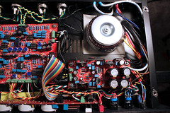
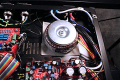
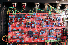
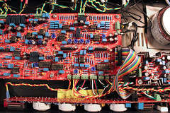
first, can you pretrim pots with them already intstalled on the board? I know it says to trim from the square pad and the wiper.
Second, Which one is the wiper exactly? :)
Third and final...is it possible or is it normal for a resistor with a known value (for example 1k) to have its value altered, after it has been installed on the board. (i think i'm getting 700ohms if i can remember)

again i apologize
 
They are NOT stupid questions.  No questions are stupid questions.

First: yes you can.  But make damn sure you know a.) how to read a circuit diagram and b.) respect the basic laws of resistance.

i.e. don't be surprised when a pot with a parallel resistor on the board doesn't read it's expected value.  Ohms law says it shouldn't, so you have to respect that.  i.e. for instance if you need to pretrim a 10K resistor to half way ( 5K ) and it has a parallel 10K resistor, then you pretrim it to half that value ( 2.5K ), for instance.  But with a little inquisitiveness and experimentation without the unit turned on, it's easy to figure out and I used this method.

Second: the wiper in almost every case of every potentiometer ever built, is the middle one.  Also, it's the one that, with a multimeter connected, produces a change.  i.e. with a multimeter connected, turn the trimpot or pot.  Does the value change?  Then one of those pins is the wiper pin.  By elimination it's easy to figure it out.

Third: Yes, please refer again to my first response.  It's basic circuit theory.  If you have specific question about specific resistors, list them here, and I'll double check it on my board for you.

regards and good luck.
 
I am 99.9% of the way there and I was going through the last calibration, the one for T2 right channel.  I got an AC reading at TP11 but zero at TP12. 

For the T1 calibration, I did get readings at TP11 and TP12 (and did complete the calibration) so there is connectivity to TP12. 

I find schematics a bit bewildering so that is about as far as I got.  I did try to see if I could get a reading by moving a bit closer to the switch so I tried to get a reading between R56 and ground.  Nothing there either.  That was pretty much it for the random voltmeter reading approach.

Also I am getting some pretty decent "guitar amp style" hum especially when I turn the output gain up.  Not sure if they are related and I saw someone else had a hum issue, so I will check more once I get this one nailed down.  Thanks for any advice. 
 
On the schematic....i understood that there was a typo.... That r132 was in fact vr16... The graph on the schematic says that it should be pre trimmed to 36k but vr16 on the schematic itself says it should be 6k.. Any ideas? Also what it's best to do with the pots that don't have a pretrim level stated? Again, any help would be greatly appreciated!
 
Bmaughan, for the no pretrim level stated pots, what I did was just install them in their factory state.  If there was a pretrim recommendation I followed it but during the final calibration step you will retrim most of those no level stated pots.
 
I just followed the build guide where it said:
"With the unit in 2:1 ratio setting, export a 1Khz test tone through the unit and back into the DAW. Adjust your DAW levels so the return from the compressor in the DAW reads approx -10dbfs. Now adjust the threshold on the compressor until there is about 10db of compression (DAW input level should now read approx -20dbfs).
Now increase the level of the test tone by EXACTLY 10db (I use a gain plugin to do this, most DAW’s should have one). Adjust VR16 until there is only 5db of gain on the output of the compressor (DAW input should read -15dbfs).
Repeat this entire process for the 4:1 and 10:1 settings. Also repeat the meter calibration (Step 4) in between each step."

It was an iterative process but it just takes a few minutes.
 
I did some more testing on the ground loop hum and I found the following.  Re: an earlier thread, I was able to confirm that all parts of the case were connected to ground.  The ground pins of the in's and out's were also connected as were the boards' 0V pins. 

If the signal path is: instrument with balanced outs > SB4000 > soundcard, there is hum.
If the signal path is: pre-recorded audio sent from DAW out through soundcard > SB4000 > back to soundcard, the hum is gone.

Here are some photos if this helps.  A few notes: the wire colors are reversed on one of the outs but the wiring is as required.  Also, the mono/stereo sidechain is disconnected as during the very last 5 minutes of soldering I grazed the switch with the iron which made it stick in the mono position (argh).  So it is disconnected (stereo) until I buy another switch.

6067065108_733220affe_m.jpg


6067065146_5768ab7856_m.jpg


6066520815_925042f903_m.jpg


6066495667_b111145370_m.jpg


No progress on figuring out why TP12 is not sending voltage.
 
Looks like those photos don't expand to give detail so here is the Flickr link.
http://www.flickr.com/photos/58425520@N02/
 
Wembley said:
I am 99.9% of the way there and I was going through the last calibration, the one for T2 right channel.  I got an AC reading at TP11 but zero at TP12. 

For the T1 calibration, I did get readings at TP11 and TP12 (and did complete the calibration) so there is connectivity to TP12. 

I find schematics a bit bewildering so that is about as far as I got.  I did try to see if I could get a reading by moving a bit closer to the switch so I tried to get a reading between R56 and ground.  Nothing there either.  That was pretty much it for the random voltmeter reading approach.

You need to look on the schematic (Bottom left hand side) at the parts that are between TP11 and TP12 and investigate.  Somewhere between these two test points, you have a bad solder joint or bad connection on your ribbon cable.

Regarding hum - please define "instrument".  What "instrument" are you plugging into it?
 
Thanks Ruckus - I will check those parts of the board again.  The instrument I used as a test case was an Elektron Machinedrum which has balanced outs.  I also used another instrument by the same company with balanced outs to determine if the hum persisted across instruments (it did).  I also was able to rule out the cables as they were used in the soundcard > SB4000 > soundcard test and there was no hum. 
 
Hey has anyone had any luck with the NTE1549. never heard any reports. I would like to know before i start powering this thing up.
 
Sorry to bump....but, anyone know any reason why this wouldnt work. I know ruckus said that he didnt think anything would blow up...i guess i'm just looking for a more encouraging answer :)
 
Finally got it all wired up, took so long for the 14awg star ground wire to arrive. But i'm getting mixed test results

+15v = 13.3
+12v = 16.7
-15v = 13.5
-12v = 16.4

Should I try VR's in VR18 & VR19 instead of the fixed resistors?
 
Just an update on my previous test. The above voltages were taken from the '+' & '-' test points, i.e TP13 & T15.

When I stick one probe onto TP14 and measure the pads at J14, I get the correct voltages:

+15V = +15.3
+12V = +11.9
-15V = -15.0
-12V = -12.1

Is this correct or do I have to measure from the test points TP13 & TP15 to get the results of -/+15V & -/+12V? 
 
Hey.... I need some help. I'm having the same problem as Jandoste. I believe that's his name. But on the -12v output of the power supply I'm getting a reading of -19v. I tried swapping regulators as this was the conclusion of that jandoste's thread. But still I have -19. I tried putting a 1k load on it as was recommended and I got -12. so with a load it seems about right. I want to make sure I'm go to go with that. I have correct voltages for all the others with out loads so that seems wierd. Any explanations, thoughts or advice would greatly appreciated. I just want to make sure its ok to proceed. Let me know... Thanks!!!
 
bmaughan said:
Hey.... I need some help. I'm having the same problem as Jandoste. I believe that's his name. But on the -12v output of the power supply I'm getting a reading of -19v. I tried swapping regulators as this was the conclusion of that jandoste's thread. But still I have -19. I tried putting a 1k load on it as was recommended and I got -12. so with a load it seems about right. I want to make sure I'm go to go with that. I have correct voltages for all the others with out loads so that seems wierd. Any explanations, thoughts or advice would greatly appreciated. I just want to make sure its ok to proceed. Let me know... Thanks!!!

What brand did you swap regulators with? Did you make sure it wasn't a St Micro?
 
Back
Top