SB4000 Support Thread

GroupDIY Audio Forum

Help Support GroupDIY Audio Forum:

This site may earn a commission from merchant affiliate links, including eBay, Amazon, and others.
Are sockets not included with the Quad kit? they aren't listed on the BOM and the only photos and info i have about this is from here : http://stereodramadiy.blogspot.com/2012/07/sb4000-quad-vca-part-i-populating.html

I have pins to attach to the bottoms of the boards. But no sockets. Or is that just something i need to order?
 
Hey quick one about that project.

1. If I don't want the bar led vu meter (because I don't care to read the output), Can I simply left this part of the control board unpopulated? It will left plenty of juice, too, on the 12v psu and since I plan making my own panel, it will be easier to cut out round hole than rectangular ones  ;D

2. I was looking at the drilling pdf on first page. There is some pilot hole for the pilot pin of each pots and swiotches. Out of curiosity, why not simply cut out the pilot pins?

3. I just noticed the spacing isn't same than the GSSL so all cases available will not fit with the SB4000, right. I don't think there is any other supplier other than the front panel on Serpent audio website, right?

Thanks
 
walkz187 said:
Harpo said:
buildafriend said:
sdrjones said:
etheory said:
Photos would be very useful however ;-)

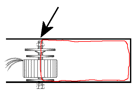
Here are some photos of my transformer + mounting kit - I think it's pretty standard.

As I said, my main concern is whether it will be a problem if the top of the mounting washer touches the top of the chassis.

A Nylon bolt was mentioned which seems sensible - do you think this will be strong enough to hold the transformer in place?

Many thanks for your help!

mine is definitely hitting the top of par metal chassis. I am about to start wiring. I'll let you know if the bolt hitting the chassis is an issue.
You don't want a conducting bolt touch the top of a conducting case. This will make a (unfortunately shorted) single turns secondary winding and fry the primary winding of your toroidal transformer that cannot deliver the current demand of this shorted secondary winding. With a little luck your mains fuse will blow faster.
Just cut the bolt to the min.required length. Maybe glue some insulating material to the top of your case to play safer.
Toroid_mounting.gif
I all I'm up to mounting my transformer. Is there a need to screw the bolt from the outside of the chassis? What other mounting options are there?
I'm concerned that with the bolt protruding thru the bottom. This will cause scratches on other gear sitting in my rack and may not even fit.
I'm using a 19in case 1 ru.  Any help or ideas would be great.

Thanks

Hi,
i have returned to this project after some time. Can anybody advise on a few question i have regarding the mounting of the transformer.
i'm using a 1 RU, space is a little tight.
Do i need to have the bolt screwed thru the bottom of the RU per the above image?
Could i have explaining from the bottom to top.  Bottom of transformer the bolt, washer ,then rubber protector. now on on top of transformer  have the second rubber protector, then metal shield protector, then screw on bolt? The bolt would not protrude externally out of the RU. The Bolt would only support the rubber and metal shields.
Then to secure in place could i use some strong double sided tape? are there dangers using double sided tape?

i would really appreciated any direction, as this has baffled me for sometime.

Thanks,

 
Hi There,

I am having some trouble getting the 12V and -12V voltages from my power supply board. The +15V and -15V are working perfectly, however all of my 12V and -12V outputs are showing +6V and -6V.  I have searched through the thread and measured the  input and output of the voltage regulators with the following results

7812 : 20V input 6V output
7812: 20V input 6V output
7912: -20V input -6V output

Its strange that both of the 7812's are showing 6V outputs, any help in diagnosing this is greatly appreciated!
 
Hi, finally completed my compressor after working on and off for several years! It's sounding really great.

Two questions:

- I am a little confused about how to calibrate THD. I built mine from the serpent kit (no quad vca). I didn't pretrim V3/V4  to anything, so I fed a 1kHz tone with gain knob at 0. I looked at a spectrum analyzer and adjusted V3 & V4 so the 2kHz peak dropped as low as possible.  Is this as much as I can do?

- My LED meter only shows the peak value - only one LED at a time. So if the meter is maxed out in the red, it only shows the top red led. I watched some videos of other people demoing their units and saw their LED meters filled out. I actually don't mind it the way I have it, but just wondering if anyone else had encountered this issue? *EDIT* Looks like JMP7 controls whether graph shows in dot or bar mode. I didn't realize there was an option.
 
"I'm concerned that with the bolt protruding thru the bottom. This will cause scratches on other gear sitting in my rack and may not even fit.
I'm using a 19in case 1 ru.  Any help or ideas would be great."

I use "JB Weld" or a 2 part epoxy to epoxy the bolt to the bottom of the case. Make sure you grind off the paint so the epoxy can stick to the metal case.
 
hello ! can i have the value of :

R76/R96
VR3/VR4
VR1/VR2
R38/R49
JMP1/JMP4
JMP2/JMP5
JMP3/JMP6
R132
JMP8/JMP9
R77/R121
R83/R125
R82/R85

For dbx 202X & dbx 2001 Vca please ?

thanks

i
 
Hi ))))


I know about electronics & this is not my first project.

As I am about to order, just a few questions:

a)
I've been parsing the whole thread.
Is there still the hint written about cutting traces for being able to connect the CnB mod on the boards?
Did anyone do the mod successfully? This mod is a must for me, as I will use the comp on my mix bus live. 

b)
ruckus328 said:
Schematic & some other items now posted in the first post.  Enjoy:)
I can not find the schematics. Where are they?
I would need them for debugging and for being able to get sure my mods will do no harm ect.

c)
If I order the blank boards only, how many Quad VCA boards do I need? Two right?
With the Quad VCA, will I still get that "cocaine topping sound"?

d)
Did anyone do a mod to choose between different VCAs on-the-fly?

e)
What are the dimensions of the boards? I am wondering if I could make a little bit smaller then the stated minimum of 1he 8inch/200mm boxing. Maybe about 4cm smaller? I see some air in the pics around.
How deep is your love?

f)
Compared to the Pcbgrinder GSSL, that one is in rev 11. The SB4000 is in rev 5. Why that difference?

Those of you who have build both, is the SB4000 better in every way?
Or is there something you prefer in the GSSL? Probably a silly question ...

There are many vids showing the GSSL off, some the SB40001 but only a few the SB4000 ...


thank you, happy for any reply!
 
Hi All

I built the SB4000 about 1 year ago and did a quick calibration at the time. now i really want to use the SB 4000 on my mix bus and wanted to fully calibrate the system.

I built the quad VCA version with THAT2181B chips. Hairball GR meter and everything else was stock supplied by serpant audio or mouser per the BOM.

i have a few issues that I'm hoping i could get some help with, firstly i cannot confidently say whether SSL turbo mode/Side chain even works. but there is some difference i have noticed in the way the signal is be treated. secondly HPFs, T1 and T2 modes don't seem to be working either and lastly i need help with some calibration issues I'm having below.

GR meter working
Threshhold working
Ratio working
Attack working
Release working
Gain working

Calibration steps
1) Power Supply: completed
2) Unity gain: completed
3) CV Levels: i get no voltage at TP10, tried the internal sedition both in and out. but still no TP10 voltage.
however whenever i toggle between internal sidechain button. i have noticed there is 2 different type of summing going on. with a 1k sine tone i pan left and right from the centre GR drops almost by 1/2. so 8db down down nearly 4db. i push the button and engage setting 2. with the same setting threshold, ratio, attack and release settings GR remains stable when centred or panned. according to this you tube video" https://www.youtube.com/watch?v=EQD8GPhFGYE "I'm getting the opposite to how the SSL compressor should be reacting to the centred signal.

4) Meter/Ratios: Completed close enough

5) Ratios: Completed :Completed close enough

5) T1 & T2 Filters: not attempted yet - but cannot seem to get HPF or T1 and T2 to work. doesn't seem to be compressing any differently.  tried with drums and thought i should notice it easily on the kick drum withe the HPF'S. but nothing.  but again not entirely sure whether i need to be in side chain mode to be able to use HPF's. which i do not think is working correctly. so any help here would be good?

5) THD: not attempted yet

6) Bargraph Adjustment:I cannot get enough adjustment on VA15. When pushing 1k sine tone in to the sb4000 at 1.288 Vac or +4dbu/ 0Vu. On the bar graph meter on the sb4000 the va15 runs out of at -6VU

Can anybody give me any pointers to why this?

Thanks
 
walkz187 said:
Hi All

I built the SB4000 about 1 year ago and did a quick calibration at the time. now i really want to use the SB 4000 on my mix bus and wanted to fully calibrate the system.

I built the quad VCA version with THAT2181B chips. Hairball GR meter and everything else was stock supplied by serpant audio or mouser per the BOM.

i have a few issues that I'm hoping i could get some help with, firstly i cannot confidently say whether SSL turbo mode/Side chain even works. but there is some difference i have noticed in the way the signal is be treated. secondly HPFs, T1 and T2 modes don't seem to be working either and lastly i need help with some calibration issues I'm having below.

GR meter working
Threshhold working
Ratio working
Attack working
Release working
Gain working

Calibration steps
1) Power Supply: completed
2) Unity gain: completed
3) CV Levels: i get no voltage at TP10, tried the internal sedition both in and out. but still no TP10 voltage.
however whenever i toggle between internal sidechain button. i have noticed there is 2 different type of summing going on. with a 1k sine tone i pan left and right from the centre GR drops almost by 1/2. so 8db down down nearly 4db. i push the button and engage setting 2. with the same setting threshold, ratio, attack and release settings GR remains stable when centred or panned. according to this you tube video" https://www.youtube.com/watch?v=EQD8GPhFGYE "I'm getting the opposite to how the SSL compressor should be reacting to the centred signal.

4) Meter/Ratios: Completed close enough

5) Ratios: Completed :Completed close enough

5) T1 & T2 Filters: not attempted yet - but cannot seem to get HPF or T1 and T2 to work. doesn't seem to be compressing any differently.  tried with drums and thought i should notice it easily on the kick drum withe the HPF'S. but nothing.  but again not entirely sure whether i need to be in side chain mode to be able to use HPF's. which i do not think is working correctly. so any help here would be good?

5) THD: not attempted yet

6) Bargraph Adjustment:I cannot get enough adjustment on VA15. When pushing 1k sine tone in to the sb4000 at 1.288 Vac or +4dbu/ 0Vu. On the bar graph meter on the sb4000 the va15 runs out of at -6VU

Can anybody give me any pointers to why this?

Thanks

Any help guys? Even if it's to point me in the right directions to know if my side Cha in is working?
 
press said:
a)
I've been parsing the whole thread.
Is there still the hint written about cutting traces for being able to connect the CnB mod on the boards?
Did anyone do the mod successfully? This mod is a must for me, as I will use the comp on my mix bus live. 

b)I can not find the schematics. Where are they?
I would need them for debugging and for being able to get sure my mods will do no harm ect.

Hi here is the schematic that i found on http://wiki.diyrecordingequipment.com/projects/sb4000-gssl/ (great site for DIY people)
http://dl.dropbox.com/u/4740474/SB4000_Production/SB4000_REV4_FORUM.pdf

I also  want to build CnB rev6  here You can find info http://groupdiy.com/index.php?topic=61934.0
but i'm thinking to create a new board from this schematic. http://www.livingnote.com/prodigydocu/cnb/CnBSchematicR6.pdf

About cutting trace you can check the schematic and then You will know why this should be cut.


cheers

PS: let me know how the work goes on ;-)
 
EmptyMusicBox1 said:
hello ! can i have the value of :

R76/R96
VR3/VR4
VR1/VR2
R38/R49
JMP1/JMP4
JMP2/JMP5
JMP3/JMP6
R132
JMP8/JMP9
R77/R121
R83/R125
R82/R85

For dbx 202X & dbx 2001 Vca please ?

https://dl.dropboxusercontent.com/u/4740474/SB4000_Production/SB4000_REV4_FORUM.pdf

I think that on the schematic You will find what You looking for ;-)

cheers
 
konqret said:
https://dl.dropboxusercontent.com/u/4740474/SB4000_Production/SB4000_REV4_FORUM.pdf

I think that on the schematic You will find what You looking for ;-)

cheers

Thank you but it's only for: dbx 202 black can & dbx 202c gold...

 
Greetings!
I finished my SB4000 a few days ago and finished most of the calibration process. I can't seem to get any response from T1 or T2 on the HPF. Pots VR5, VR6, VR9 and VR10 appear to have no effect on the signal or AC readings. Any suggestions?  Thanks.

Update: I've also noticed that the right channel is -3dB quieter than the left channel in bypass.
 
Hi everybody !

I just have finished my sb4000, and guess what !
I have a problem ! \o/

When I first powerd up the psu part only, everything was great, power rail were ok, everything seemed to be on its good way !

There I have connected the psu to the main pcb, after everything else was wired, and guess what : two resistors just went to smoke

My first smoke in a build \o/

Anyway, r182 and r183 just went rogue!

Where does it can come from for you?
 

Latest posts

Back
Top