Hey guys,
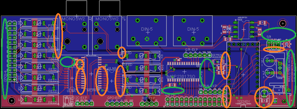
Attached is an image of my first design in Eagle. I'm a complete noob at PCB layout and an amateur at electronics in general, so I'm prepared to be brutalized. Any comments general or specific would be much appreciated before sending this off and twiddling my thumbs for a few weeks.
Its a simple circuit, it uses a Teensy3.1 microcontroller to control an i2c expander driving 12 reed relays, with another i2c expander handling simple inputs. There is also a Midi I/O circuit with optoisolator connected to one of the Serial busses. The 2x13 headers are meant to connect to a DB25-IDC connector, to save me PCB real estate and cost. I know it looks like a lot of wasted pins, but this is all designed to interface with an Avid Profile live mixing desk, so I'm working with their GPIO pinout.
The bottom layer is entirely a ground plane and the top layer has a 5v rail along the bottom and of the red traces larger than 10mil are power.
One of my main points of uncertainty is the power layout. Would it be better just to do a copper pour over the entire top layer? Or should I keep it as is and add more ground plane on the top layer?
Anyway, like I said I'm a beginner so don't hesitate to mock my horrific layout")
Thanks!
Adastra
Attached is an image of my first design in Eagle. I'm a complete noob at PCB layout and an amateur at electronics in general, so I'm prepared to be brutalized. Any comments general or specific would be much appreciated before sending this off and twiddling my thumbs for a few weeks.
Its a simple circuit, it uses a Teensy3.1 microcontroller to control an i2c expander driving 12 reed relays, with another i2c expander handling simple inputs. There is also a Midi I/O circuit with optoisolator connected to one of the Serial busses. The 2x13 headers are meant to connect to a DB25-IDC connector, to save me PCB real estate and cost. I know it looks like a lot of wasted pins, but this is all designed to interface with an Avid Profile live mixing desk, so I'm working with their GPIO pinout.
The bottom layer is entirely a ground plane and the top layer has a 5v rail along the bottom and of the red traces larger than 10mil are power.
One of my main points of uncertainty is the power layout. Would it be better just to do a copper pour over the entire top layer? Or should I keep it as is and add more ground plane on the top layer?
Anyway, like I said I'm a beginner so don't hesitate to mock my horrific layout
Thanks!
Adastra