SSL 9K & 4K (E Series) 500 / 51X NEW BOARDS Mic Pre Thread 2011

GroupDIY Audio Forum

Help Support GroupDIY Audio Forum:

This site may earn a commission from merchant affiliate links, including eBay, Amazon, and others.
Brilliant! Thank you very much - seems like something deep and dark is pointing towards buying those LEDs from mouser then.

Another question that I think is also equally ridiculous - apologies. This board is a 51x board (as its the 4.2 version), but the extra two pins at the bottom don't seem to be going anywhere on the PCB. I have a cheap Midas chassis that I could use, but there's no way this is going to fit in there...right?! I was going to go down the 51x chassis route, but sadly if I could save a bit of expenditure it would be great.
 
m1lkybar said:
Brilliant! Thank you very much - seems like something deep and dark is pointing towards buying those LEDs from mouser then.

Another question that I think is also equally ridiculous - apologies. This board is a 51x board (as its the 4.2 version), but the extra two pins at the bottom don't seem to be going anywhere on the PCB. I have a cheap Midas chassis that I could use, but there's no way this is going to fit in there...right?! I was going to go down the 51x chassis route, but sadly if I could save a bit of expenditure it would be great.

You can cut those extra fingers off. I do. They're not needed. They're there so it will fit easily and nicely into a 51x rack if you happen to have one.
 

Attachments

  • SSL_11-2_CROP.jpg
    SSL_11-2_CROP.jpg
    169.8 KB
Ricardus said:
You can cut those extra fingers off. I do. They're not needed. They're there so it will fit easily and nicely into a 51x rack if you happen to have one.

Thank you very much!
 
Hi, me again...

I'm having some issues getting one of my boards working. I populated them both at the same time, and soldered each component in at the same time (but I appreciate my soldering isn't great!), but for some reason one board works - and the other doesn't. My working board is a little lower in gain than I thought it would be, but I'll try solving that later.

I'm not receiving an amplified signal out of the board, and if I push the gain on my interface input then I can get the quietest of signals that is just about audible if I tap my SM57. I am getting full level short pops from the switches as I turn them on/off (which I'm expecting), but this doesn't register on the meter board - and on my working board, the switches register a transient on the meters. I've tried measuring the voltages but I'm not really too sure what I'm looking at/for, but I seem to have -15v at R76 but -0.81v at R77 (working board is -15/+15 at R76/R77). Similar readings at the bridge rectifier too. The only red flags I can think of are that I bought my MAT02h off eBay (sorry!), and my soldering could be a bit dodgy. Here's two pics, the non-functioning board is first, the functioning second.

Non-functioning:
b6yDw2ds.jpg
https://i.imgur.com/b6yDw2d

ewogeMEs.jpg
https://imgur.com/ewogeME

Functioning:
vu0eDmos.jpg
https://imgur.com/vu0eDmo

9iMdHdgs.jpg
https://imgur.com/9iMdHdg

Sorry to throw something probably obvious onto the community, this is my first bit of serious soldering work after making said guitar pedals. Grateful for any potential help!
 
m1lkybar said:
Hi, me again...

I'm having some issues getting one of my boards working.

1) check for any solder bridge or short
2) check all resistor values, sometimes is easy to make the mistake of using 470K instead of 470R or vice-verse
3) check all lytic caps polarity orientation
4) check all caps values

If you are in doubt about the MAT02, take it out and measure HFE on both sides, it's a super matched transistor pair, so each side should have the same HFE or pretty close.

Go to Ebay or aliexpress and buy an MK-328 Tester, it's pretty cheap an a great component measuring tool
 
Ricardus said:
I'll download those pics and have a look when I have some time, but some look a but out of focus, which makes it hard to help you.

Yes that another thing, you should post pictures that people can see, not pics so oversized that they are bigger than the screen and scare the dog.

You will loose help, for not posting  sized photos for the thread as most people will not even see them
 
Oh sorry my apologies, it's a lot bigger than I thought it would be in-line. I'll take some better photos tomorrow in better lighting so I can use a higher aperture, and sort out the formatting.

Thank you for your help Whoops, I've been going through the resistor values at the moment which seems to be taking me a few days. Couldn't see any solder bridges, or any issues with cap polarities - although it was difficult to see the MUSE spec polarity. I think some of my capacitor legs don't have solder flowing through to the other side of the board, so I'll reflow those too. If I get to the end of this weekend without any resistor issues, I'll take out the MAT02h and do a readout on the HFE. It turns out my gain pot on my functioning preamp doesn't actually do anything, but I can get a healthy signal from a guitar amp. 
 
Ricardus said:
So I looked over the underside of the board that isn't working and I see about 2 dozens leads that are too long and need to be trimmed. The soldering isn't awful and I don't see any obvious bridges.

What's up with the gigantic R1 and R2?

Yes, you should trim those legs, theres a lot on the "functioning" board and a few in the other.

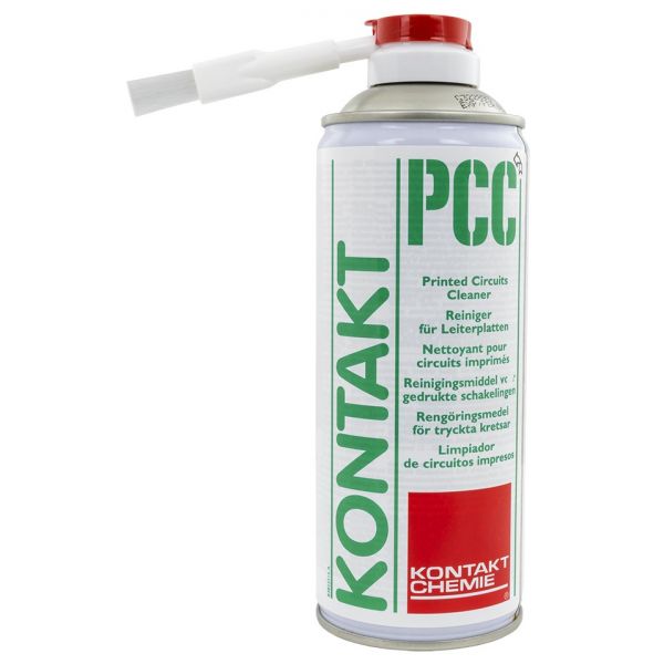
Also Clean the solder side with alcohol and rub with a tooth brush.
Os use something like this, it's the same thing in the end:

241291_3_kontakt-chemie-spray-limpeza-circuitos-impressos.jpg
 
m1lkybar said:
I think some of my capacitor legs don't have solder flowing through to the other side of the board, so I'll reflow those too.

That happens sometimes, I normally always reflow both sides of the PCB in all the components where it's possible. Do that to all

m1lkybar said:
If I get to the end of this weekend without any resistor issues, I'll take out the MAT02h and do a readout on the HFE. It turns out my gain pot on my functioning preamp doesn't actually do anything, but I can get a healthy signal from a guitar amp.

If the Gain pot doesnt do anything something is wrong also with that one.
As for the MAT02 you can also change the one from one channel to the other.

You can also get some BC550C (or any other general purpose NPN) match 2 of them for HFE and use them in place of the MAT02 just to try it out and for testing.
It might also work good enough, some people glue 2 NPN matched transistors for thermal coupling and use that instead of MAT02
 
hello good to all !!!
Anyone please have some full scale s500 front panel template in .pdf or some other format ??
Thank you so much.
 
Hi!

Are wima MKS4 series 2,2uf LEAD SPACE 22,5mm ok for input caps? lead space is ok as for the board i have. But the series MKS4 is ok? or the series you try does not matter much?

http://www.banzaimusic.com/WIMA-MKS4-2-2uF-250V-LS22-5.html
Jay x
I have been using the same cap from the same series except 100 volts. The 22.5 lead spacing is correct. It looks like the one you've linked to is a little wider and a little taller, but the board will accommodate the width perfectly, and the height is no issue. The length is exact and the lead spacing is correct so you're fine.
 
Hi!

The caps with values in picofarads, ¿can be ceramics? (cog/npo). or must be wimas mkp/fkp?...
 
Back
Top