You are using an out of date browser. It may not display this or other websites correctly.
You should upgrade or use an alternative browser.
You should upgrade or use an alternative browser.
Telefunken V72 DIY
- Thread starter CJ
- Start date


Help Support GroupDIY Audio Forum:
This site may earn a commission from merchant affiliate
links, including eBay, Amazon, and others.

CJ
Well-known member
OK, I had a weird experience with the DIY V-72 plate choke. I wound the coil and laced only the E lams alternating back and forth to see what kind of henries I woulds get with this method. If it worked, I wouldn't have to worry about keeping a gap from drifting. This is the way Marinair inputs and Lundahl transformers are laced, only with U lams, not E's. Well, I lace it up, put it on the B-K inductance bridge and i get nothing! Crap. Did I break a lead again when I laced it up> I get out the ohm meter and it dosen't give me a reading. Just blinks back and forth on weird values. Crap! I broke another coil. So I cut off all the turns with the exacto and start over. :evil: I wind another coil. Lace it up. SAME THING! A broken winding! So this time I unwind every turn by hand to find the break and there isn't any! :evil: :evil: What the hell?
So I wind another coil, (This is number four, folks) lace it up, SAME THING! :twisted: :twisted: :twisted: OK, something is up. Is the voltmeter putting a torque on the windings? Are my lead breakouts breaking? I re-solder the leads, same thing. Hmmmmm. :idea: Lets try the good ol Gen Rad inductance bridge. Bingo! Mucho henries! I measure the dcr and the meter still flips out. Turns out that when you lace the E lams without the I bars, the inductor does strange things to digital ohm meters and inductance bridges. So I threw out two good coils by mistake. Live and learn.
Anyway, here are some more pics.
Good news. With the drill motor, I wound it in ten minutes instead of four hours. Holdong the wire between some kleenex adds additional tension to the wire, as it's kind of like a tug o war. The tensioner adds tension, and I am probabling doubling that with my fingers. This makes the windings tighter which means more turns. Youi can actuallty feel the wire stretch a little when you wind. Also, you can detect kinks by holding the wire between your fingers. The faster you wind, the less kinks. The centrifugal force teends to straighten out the wire a little.
Here is the final coil:
http://vacuumbrain.com/The_Lab/TA/Telefunken/V-72/coil_final.jpg
I laid down some old tape from a UTC to lay the leads on.:
http://vacuumbrain.com/The_Lab/TA/Telefunken/V-72/lead_1.jpg
BTW, that Kapton tape is a real bitch to slit with scissors, so I figured out another way. You lay a strip down on a smooth surface and use an exacto:
http://vacuumbrain.com/The_Lab/TA/Telefunken/V-72/tape_cut.jpg
To solder the fragile magnet wire, first wrap it around the breakout wire. Don't tin it. The larger wire will act as a hintsink and keep you from frying the wire:
http://vacuumbrain.com/The_Lab/TA/Telefunken/V-72/leads_2.jpg
After soldering the wires, torque them down with some more tape. Mylar would be better than Kapton, but I have not bought any yet:
http://vacuumbrain.com/The_Lab/TA/Telefunken/V-72/lead_3.jpg
I have to find a way to keep the I bars in constant tension with the E lams so the inductance does not change. You want to use a non ferrous metal to do this. I thought about brass core brackets and aluminum tie plates, but then I had another idea. There was some scrap Lucite laying around here so I spooled up the mill and this is what I came up with:
http://vacuumbrain.com/The_Lab/TA/Telefunken/V-72/brackets_1.jpg
Those troughs will hold the lams in position. I machined the Lucite to get a press fit. I will put some 1/4 28 bolts thru there with some split locks to keep a constant tension. You do not want to use epoxy with nickel, as the flux will actually cause the nickel lams to expand, which will cause mechanical>electrical distortion. This expansion is also one of the reasons why lams make noise sometimes.
Here is the choke and the brackets:
http://vacuumbrain.com/The_Lab/TA/Telefunken/V-72/brackets_2.jpg
Just happens to fit nicely into this old UTC can that was a previous take-apart victim:
http://vacuumbrain.com/The_Lab/TA/Telefunken/V-72/can_1.jpg
see ya!
cj
ToobieSnack
Well-known member
- Joined
- Mar 3, 2005
- Messages
- 493
WOW the info here is excellent.
Toobie Newbie doo,,, have questions /observations
couldn't you just plug your drill into a variac and have variable speed control without hacking up your drill?
on the subject of reforming capacitors and the variac thingy
If you are firing up an entire unit complete with power trafo the trafo will convert the AC to dc and this will work, right?
ALSO
couldn't you run the variac output through a power transformer and also have DC on the output of the transformer? (not a ideal/ solution but it would work right?)
ok now on to other questions
ok I'm a bit of a newbie so bear with me and i hope these aren't too stupid
I followed the pics closely and:
is this one single strand of wire divided into 3 sections?
I'm pretty sure the answer is yes, there are only 2 leads right? (choke)
how do you transition from one section to the other? Under, over, through? (through a notch in the dividers, right)
the winding process :
do you wind one section completely or
one layer of wire per section repeating until the desired number of turns is acheived? or the bobbin is full?
also in the final stage where you mount it all to the Lucite I'm not clear on the other component ( the E/U lams and I bars i think) how are they positioned in relationship to the coils
are they signle units or layers of metal stacked? how many if so?
are they U lams? around 3 sides stacked and a stack of i bars on the 4th side?
well anyway sorry for the newbie stuff
(my eyes are dry and burning and my neck is killing me) lol
its just that ....this post reads like a good book that i can't put down and I feel somehow I've missed the the ending
i just had to know
lol
all your posts are great and thanks sooooo much
Toobie Snack
jensenmann
Well-known member
on the subject of reforming capacitors and the variac thingy
If you are firing up an entire unit complete with power trafo the trafo will convert the AC to dc and this will work, right?
ALSO
couldn't you run the variac output through a power transformer and also have DC on the output of the transformer? (not a ideal/ solution but it would work right?)
NOOOO, holy moly
You always get AC at the output of any tranny, no matter which type. A tranny converts the amount of the voltage. For getting DC you need a rectifier and at least a smoothing cap.
the easiest way to reform caps is to take a 1,5V battery, connect the cap to it ( +to+, -to-) and let them alone for some time. Just forget about this variac thing in that context. And don´t worry too much about reforming. When you buy new caps it is not necessary to do this.
Give it a try and read about how trannies work. It will make your (diy)life much more secure.
:wink:
Jens
CJ
Well-known member
Tube Snake, it is a single piece of #39 magnet wire. It passes from section to section thru a little slit I cut in the dividers. I fill up each section one at a time. The core is EI lams with all the E's on one side, and all the I's on the other, with a small gap in between made out of Kapton tape. .001 Nomex would be better. Core material is 80% Ni 625 EI sampled from Magnetic Metals in N.J.
Capacitance in a multi sectioned coil is reduced by a factor of 1/N^2, where N is the number of sections in the coil, so this coil will have 1/3^2 = 1/9 th the capacitance had I wound it all on one section. Res freq s/b around 50 kcps for this coil.
I forgot the bobbin p/n, but if you go to the Cosmo Corp web site and look in their catalog, you can find many a square bobbin for the 625 EI core.
DCR is about 2 k ohms, henries depend on how hard you press the core together, anywhere from 100 to 200 henries.
cj


CJ
Well-known member
More progress- got some brass bolts for the choke and torqued it up to 150 henries:

Then I bolted it inside that big UTC LS-68 can on the left. A triad HS-50 is sitting in the HA-100X can. After I croak, some poor fool is gonna be really confused when he tries to scrap this for parts:
http://vacuumbrain.com/The_Lab/TA/Telefunken/V-72/v72_utc.jpg
I machined some tube holders out of lucite. Gonna use coreprene pads stuffed in there to act as a dampner:
http://vacuumbrain.com/The_Lab/TA/Telefunken/V-72/v72_tubeholder_1.jpg
Leads are soldered direct-don't want no old tube socket unpleasantries.
Four pads are stuffed in there with the tube:
http://vacuumbrain.com/The_Lab/TA/Telefunken/V-72/v72_tubeholder_2.jpg
Finally ready to wire this guy up! I swear, DIY is 99 percent mechanical/purchasing and 1 percent soldering.
:guinness:
man, that transformer looks really cool.
If I was your manager, I would suggest the following:
I know you are into the classic look of the transformers, but since you've put so much time into it and have access to lucite, why not build a clear lucite container for the transformer so people can see your work? Not only will it show off the transformer, but it will make the whole project look completely insane. Is that transformer can offering a high degree of RF protection? Even if it is, I would try to see if you can get away with a clear lucite case for that thing, that would be so badass!
dave
chrissugar
Well-known member
"Finally ready to wire this guy up! I swear, DIY is 99 percent mechanical/purchasing and 1 percent soldering."
You have to suffer 99% for the 1% pleasure. :grin:
chrissugar
This is my post No. 500
:grin: :grin: :grin:
You have to suffer 99% for the 1% pleasure. :grin:
chrissugar
This is my post No. 500
:grin: :grin: :grin:
CJ
Well-known member
OK, gonna finish off the V72S tomorrow and fire it up. Burning in the caps right now. Just gotta wire the pwr cables and input x-former and I'm done.
Things got a little tighter than expected but I managed to cram everything in there.
This is the Siemens version with the split cathode resistors which increases the gain. I thought I was going to have to wire in a trim pot and trim cap on the feedback circuit, but after consulting with Winston O Boogie, I was told that 80K and 50 pf ought to get me in the ballpark. The trim pot tweaks the gain and the trim cap tweaks the high end response. Interesting to note than unlike the V76, the 72 uses DC feedback off the plate and screen of the output stage. Pos and neg feedback at the same cathode node. Supposedly the sreen feedback lowers the output impedance.
http://vacuumbrain.com/The_Lab/TA/Telefunken/V-72/burn_in_1.jpg
CJ
Well-known member
OK, this guy is finished except for the paint and labels. It fired up from the get go, but I traced the relatively simple circuit out a few times, so no surprise.
Probably the most noise free project I have ever done. I mean, when you talk into the mic, you hear your voice. When you don't talk, you hear absolutely nothing. No 120 hum, no shot noise, no brownian uncertainity noise, no bohemian interflow noise, no leaky tranvestite noise, nada. And I strapped the Peerless for a 1:26 step up ratio. It's got 90 db shielding which helps.
I always feel around for hot spots and I noticed the 80K feedback resistor was a little warm. Then I looked at the schematic and noticed why. It caries the plate voltage of V2 to ground via the 500 ohm cathode resistor. This also raises the bias on the input tube to about 2.7 volts. Interesting.
Here is stage 2 and the pi filters. Ground currents are handled by that big buss wire near the back, which is soldered directly to the chasis via a ring connector. Thats a German NOS from the fifties non polarized output cap on the right. I reformed the Elko lytics on 40 volts overnight and the leakage came way down, which means they are fine. Weird, that blue Phillips cap on the right had zero leakage from the get go. And it's been on the shelf for years. Just like me! :razz:
http://vacuumbrain.com/The_Lab/TA/Telefunken/v72_a.jpg
Not a lot of components.
Simplictity means people who know their biz.
Used big resistors becuase thats all I had.
Not exactly star grounding, more like buss grounding, but it worked, so...
Your either on the buss or off the buss. :razz: (Ken)
http://vacuumbrain.com/The_Lab/TA/Telefunken/v72_b.jpg
I win the "shortest wires from mic jack to input tranny" award.
6.04 k phantom resistors matched to the nearest ohm.
Ferrite beads and 10 pf to grounf rf supression:
http://vacuumbrain.com/The_Lab/TA/Telefunken/v72_c.jpg :razz:
cayocosta
Well-known member
Excellent CJ.
CJ
Well-known member
Thanks!
Now I get to go home and try and out tweak those rocket scientist's from the 30's and 40's, which won't be easy.
Happy Friday!
:guinness:
Now I get to go home and try and out tweak those rocket scientist's from the 30's and 40's, which won't be easy.
Happy Friday!
:guinness:
tommypiper
Well-known member
CJ, you da man, bro! Supraexcellenté. Salivatorium.
Inspiring.
Inspiring.
jensenmann
Well-known member
:thumb: :thumb: :thumb:
another strike
I´m looking forward to what´s coming next, CJ!!!
:guinness:
Jens
another strike
I´m looking forward to what´s coming next, CJ!!!
:guinness:
Jens
CJ
Well-known member
Ok I tried tweaking every component in the V72 last night and nothing I did changed the sound. Which is good. As parts age and drift, the amp still will sound the same. Those guy's were pretty bright. I changed the output cap, the first stage cap to a .1 Vitamin Q, the feedback resistor, the feedback cap, everything and no change in sound. Probably because of all the neg feedback. One thing I did do that changed the tone was put a pot in series with a .01 cap that terminated the sec. of the input x-former. This is a really cool mod that I am going to permanently install. 1 Meg audio pot will work good. The freq response of this amp is a little too good for my liking, so the pot will allow me to tweak the tone with various microphones. I guess the loading of the mic via the network is what rolls off the highs. Try it yourself on your own pre's and see what you think. With the pot turned to 0 ohms, you get a really cool old school rolled off sound.
This darn thing sounds as good as my V-76 with about half the parts and half the work. . Just less gain, that's all. But still, it has plenty of gain for even a SM57.
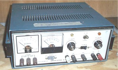
Now it's time to paint the SOB. Got some bodywork to do first, gotta plug four holes in the surplus panel. Oh what fun. That Evercoat Glazecoat is a really smooth filler, but cost 40 bucks a bottle. What color should I paint this guy?

This darn thing sounds as good as my V-76 with about half the parts and half the work. . Just less gain, that's all. But still, it has plenty of gain for even a SM57.
Now it's time to paint the SOB. Got some bodywork to do first, gotta plug four holes in the surplus panel. Oh what fun. That Evercoat Glazecoat is a really smooth filler, but cost 40 bucks a bottle. What color should I paint this guy?
MikoKensington
Well-known member
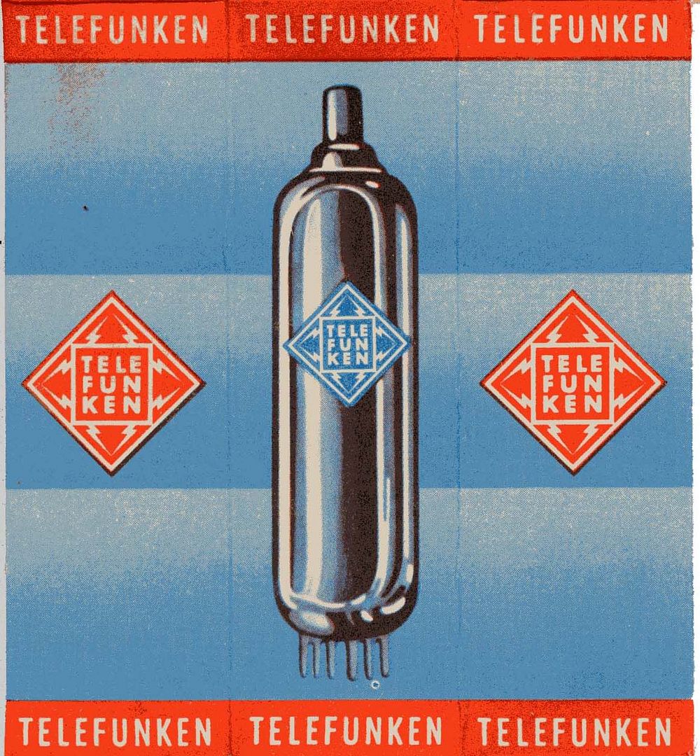
CJ this is just my suggestion but what if you painted the panel with the color scheme of an old Telefunken tube box?
CJ
Well-known member
That's the bunny!
I'll give it a shot. Lazertran transfers, eh?
Thanks for the cool idea!
:guinness:
Don't tell the DIY police.
I'll give it a shot. Lazertran transfers, eh?
Thanks for the cool idea!
:guinness:
Don't tell the DIY police.
scott_humphrey
Well-known member
Very cool, CJ. You're inspiring me to build some of these. So is this link:
http://www.tab-funkenwerk.com/FAQ.html
http://www.tab-funkenwerk.com/FAQ.html
scott_humphrey
Well-known member
CJ,
How are you varying the gain on yours (or are you?)?
Thanks in advance,
Scott
How are you varying the gain on yours (or are you?)?
Thanks in advance,
Scott
Similar threads
- Replies
- 8
- Views
- 4K
- Replies
- 3
- Views
- 3K
- Replies
- 27
- Views
- 9K
- Replies
- 22
- Views
- 3K