TG1 - advice from any one who has built it...

GroupDIY Audio Forum

Help Support GroupDIY Audio Forum:

This site may earn a commission from merchant affiliate links, including eBay, Amazon, and others.
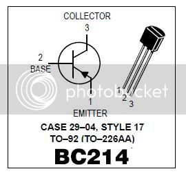
I did meter them and it kept showing me that they were positioned correct. But now it appears the EBC/CBE-labeling is wrong.
Electrochronic, so what you're actually sayings is that since the printing is incorrect, I am the first who inserted the BC214's correctly as it was labelled!
And thus wrong...  :-\
Anyway, I'll reposition them.

Which brings me to the next question: How much heat, for how long, can these (old) transistors take? I only a hand pump for desoldering so they'll feel some heat.
Should I try to borrow a good desoldering machine for this?
Or just buy new ones, being the capitalistic consumer that I am?
 
i'd say you'll be safe enough using a standard hand desolder-er... (i do love my hakko 808 though!)

you can clip on a little heatsink - like a bulldog clip to keep it cool.

give it a bit of time to cool down between legs.

good luck!
 
To me perhaps the simplest way to remove already soldered parts has been using a desolder pump. Patience and timing is the key here...

Btw, I used BC214Ls in my TGs and had to bend their legs.
Just made sure which leg had to go where and confirmed with a multimeter to be sure about the pinout. Stuffing them in the board was easy as the 'bended BC214L's" could be put in the board simply reversed (compared to normal bc214's).
 
Hi all,

I built two board, both are working, but one introduces hum into the system audible on both channels
and I really dont find the mistake i did

sigh,  nicholas
 
Hank & Nathan, Rob, Haima etc ....

BC214 = the most confusing part ever  ?

I have to say I have never run into such a mess regarding pinout orientation. I usually
rely on datatsheets , but in this case the datasheets do not agree with some of my findings.
I thought this would be worth digging a little deeper to do some fact finding regarding this
BC214 part.


MotBC214.jpg

copied directly from Motorola manufucturers datasheet, appears this is not true with the BC214
parts I have ,and they are Motorola's. I tested a few of my own BC214's in a DVM on the hfe
setting and found the orientation starting with pin 1 as CBE. Which proves opposite the datasheet, but
correct for the TG board. Had these BC214 Motorola's tested as the datasheet suggests ,
the TG silkscreening would be wrong, but this is not the case. I mistakenly was misled by the
datasheet orientation.

I still think your BC214 are reversed , the hum is a tell tale sign of pin reversal.


After physically checking a TG board , the schematic and a actual BC214A Motorola part
the labeling on the TG board is correct. CBE (Pin 1 C with TO92 flat face foward)

Your part should work fine , unless pin 1 on your device is E which would make it
a EBC not CBE. The only way to confirm this is with the hfe transistor test function on a
DMM, DVM.

The last information I posted was pulled directly off a www transistor reference page , which
has made this ever more confusing , because it does not agree with my actual
findings and suggests manufacturer specific layout which may not represent what we are dealing with here. Specifically,  regarding your part ,  regarding the BC214A Motorola I have , and the TG board we all have.. I have changed and updated that last post to represent my actual findings.

Could it be the Datasheet is wrong or maybe the spec was changed regarding orientation , I don't know
it seems to be a moving target. Rely on your DVM in this case, as Rob suggested.

At least we know the TG boards are silkscreened correctly.
 
I have a two channel unit with the nos diodes and transistors that has been in use for a couple of months. It functions correctly and sounds good, however it seems to be a little noisy compared to other units i built. the noise is only present when the unit is active. the bypass in my unit passes through the transformers but not the actual boards, and it is not noisy in this state. the noise is related to the level of the output pot, but not the setting of any other switch. everything that carries audio is sheilded, I have moved stuff around inside the unit to no avail. any ideas out there?
 
I discovered a new issue with mine tonight.  The +28VDC regulator is dropping out of regulation when I have the input and output transformers switched in circuit, but only when both channels transformers are activated.  It looks like I'm right on the threshold.  It's dependent on my line voltage, which was measuring 119VAC tonight.  Usually it's around 123VAC, but it's been really cold today and everybody is running their heaters.

I'm using an Antek 0225, which is 25VAC x 2 @ 25VA.  I measured ~31.3VDC at the input to the +28VDC regulator when I have the unit bypassed.  When I switch it to "clean" mode (no transformers in circuit), it drops to about 30.8VDC.  With the transformers in circuit on both channels, I'm reading 30.1VDC, and the +28VDC rail drops to 27.4VDC.  At that point, I get a loud 120Hz buzz at both channels which responds to the output rotary switch, so it's appearing in the audio path at the main boards.

This all make sense because when the transformers are switched in, all the relays on the bypass boards are running.  I used some Multicomp brand relays from Newark, which supposedly draw 200mW each when the coil is energized.

I'm thinking I may have to go up to a 28VAC x 2 transformer to give myself a little more of a voltage buffer.

Anybody else have any issues with voltage sag?
 
TG PSu requirement is +/- 28v output

Use 56-60vct (2x28vac) or (2x30vac) /30-50va transformer

Mark called it first.
 
The PSU schematic I have shows 25VAC, and the silkscreen on the board shows that also, but that's obviously not cutting it.


Attachments

  • PS_SCHEM.GIF
    PS_SCHEM.GIF
    34.8 KB · Views: 84
Nathan,

I see why you chose 25vac from Antek, they don't have a 28-28 or 30-30 secondary offering
wondering if your Antek 0225 is just lacking the needed reserve current. Maybe the Antek 0525 (50VA)
would solve the issue ?
 
hello,
I have the very same problem: drop outs and I am using a 25+25 VAC transformer with LM317 and LM337 regulators.
do you guys think I could use a 30 + 30 VAC transformer with no problem?
from the regulators data sheet I can see they will only accept 40VDC input MAX, and if I was to use a 30VAC I would be injecting 43VDC onto them.

any thoughts?

 
40V is the maximum differential between in and out! We use LM317T for the 48V in all our supplies. Higher differential = more heat!
 
Hi TG Builders
I have a ground problem and I"m to stupid to solve it:

I built a stereo TG Limiter, both channels work no buzz no noise if I have just one channel connected to the PSU if I connect both
I have a ground loop and I just dont find the problem  arggh !    any hints ?


nicholas
 
Back
Top